Meta Quest 2 Power Button and LED Board Replacement
ID: 169156
Description: This guide shows how to remove and replace the...
Steps:
- Hold the power button for three seconds to fully turn off your headset.
- You'll hear a power down chime, and the LED next to the power button will turn off.
- Grasp and pull on the nose section of the facial interface to unclip it from the headset.
- Grasp and pull on the top section of the facial interface to unclip it from the headset.
- Remove the facial interface.
- During reassembly, align the facial interface to the headset and use your fingers to press along the perimeter to clip it back in.
- Use your fingers to grasp the right strap near the headset.
- Peel the right strap away from the headset arm to unclip it.
- Repeat the procedure to peel the left strap away from the arm to unclip it.
- Separate the hook and loop strip on the top strap.
- Unthread the top strap from its bracket.
- Remove the head strap.
- Use a Torx T2 driver to remove the six 3.5 mm‑long screws securing the eyepiece trim.
- Insert an opening pick into the seam between the eyepiece trim and white outer shell, near the nose cutout.
- Slide the opening pick to the right along the seam to release the clips securing the eyepiece trim.
- Pry with the opening pick to release the clips securing the right side of the eyepiece trim.
- Leave the opening pick in the seam to prevent the clips from reengaging.
- Repeat the prying procedure along the left edge to release the clips securing the eyepiece trim.
- During reassembly, press your fingers along the perimeter of the eyepiece trim to clip it back in place.
- Don’t try to fully remove the eyepiece trim in this step. It’s still connected to the headset by a short cable.
- Lift the eyepiece trim slightly and tilt it towards the top edge of the headset.
- Set the trim down on your work surface, making sure not to strain the cable.
- Use the point of a spudger to flip open the black lock tab on the ZIF connector securing the face sensor cable.
- Use tweezers to pull the face sensor cable out of the ZIF connector.
- Remove the eyepiece trim.
- During reassembly:
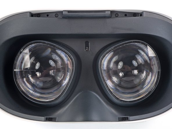
- Make sure the lens spacing matches the spacing indicator. This allows the indicator peg to sit correctly in its notch.
- If the lens spacing doesn't match the indicator, manually adjust the lens with your fingers.
- During reassembly, the face sensor cable can be tricky to connect. Follow these tips to connect the cable:
- Thread your fingers through the eyepiece trim’s eyeholes and grasp the edges of the sensor cable.
- Slide the sensor cable into the socket until the first set of tabs rests in the socket. This should flip the lock tab down partially.
- Use a spudger to press the lock tab down towards the cable to lock it in place.
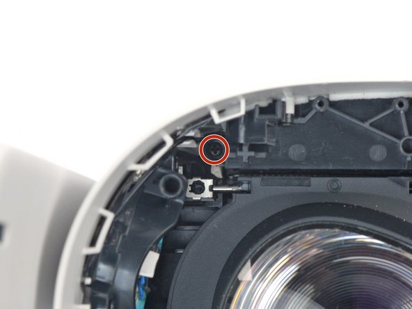
- Use a Phillips screwdriver to remove the five 7.7 mm‑long screws securing the front cover to the headset:
- One recessed in the top-left corner
- One recessed in the top-right corner
- Three along the lower edge
- The front cover is still held in place by clips along the bottom and side edges.
- Insert an opening pick into the seam between the bottom edge of the front cover and the headset.
- Pry with the opening pick to release the front cover clips.
- Slide the opening clip along the seam and pry to release all the clips securing the front cover.
- Remove the front cover.
- Use a pair of tweezers to grasp the metal neck of the top-right antenna cable.
- Lift the antenna connector straight up to disconnect it.
- Guide the antenna cable out of its metal clip holding it in place.
- Use a Phillips screwdriver to remove the three screws securing the battery cable bracket:
- One 4.4 mm‑long screw
- Two 2.3 mm‑long screws
- Use tweezers or your fingers to grasp the battery cable bracket.
- Twist the cable bracket slightly so that its bottom left corner unclips from the motherboard.
- Remove the battery cable bracket.
- Use a spudger to pry up and disconnect the battery press connector from the motherboard.
- The battery press connector can disconnect accidentally during reassembly. Check this connector before you attach the bracket.
- Insert one arm of a pair of tweezers under the metal neck of the black antenna cable near the fan assembly.
- Lift the antenna connector straight up to disconnect it.
- Guide the antenna cable out of its metal clip holding it in place.
- Use a Phillips screwdriver to remove the eight screws securing the antenna assembly to the headset:
- Four 4.4 mm‑long screws
- Two 4.8 mm‑long screws
- Two 10.7 mm‑long screws
- Use your fingers to flip up the antenna assembly enough to access the cable underneath it.
- Use tweezers to unclip the antenna cable from its metal clip.
- Remove the front antenna assembly.
- Use tweezers to grab the fan connector and carefully slide it out of its socket.
- Use the point of an opening pick to loosen the adhesive securing the LED flex cable from the top of the fan assembly.
- Remove the two screws securing the fan assembly to the headset:
- One 4.4 mm‑long Phillips screw
- One 3.6 mm‑long Torx T2 screw
- Lift the fan assembly and remove it.
- Use a Phillips screwdriver to remove the four 2.3 mm‑long screws securing the heat sink to the motherboard.
- Use your fingers to lift the heat sink and remove it.
- You may feel a bit of resistance. This is normal since the midframe is slightly bonded to the heat sink with thermal paste.
- You can reuse the thermal paste if you keep it clean. Otherwise, use a spudger to scrape off the old paste and apply a small amount of thermal putty or viscous thermal compound (such as K5 Pro) to the processor.
- During reassembly, stop here and check if these twelve connectors are properly connected to the motherboard:
- Two speaker connectors
- Seven ZIF connectors
- Two press connectors
- One antenna connector
- There are additional connectors on the motherboard, but they shouldn't be connected at this point.
- Use tweezers to grip the left speaker cables at the base of their motherboard connector.
- Lift the connector gently straight up to disconnect it.
- During reassembly, use the flat end of a spudger to press the speaker cable into the rubber holding clip.
- Repeat the disconnection procedure for the right speaker connector.
- During reassembly, use the flat end of a spudger to press the speaker cable into the rubber holding clip.
- Use tweezers to gently peel the black tape covering the two top flex cables.
- Set the tape aside to be reused during reassembly.
- Use a clean fingernail or a spudger to pry up the lock tab securing the top left camera cable.
- Grasp the top left camera cable with tweezers and slide it out of its ZIF connector.
- Move counter-clockwise around the motherboard and disconnect the remaining six ZIF connectors:
- Power button and LED board
- Bottom left camera
- Bottom right camera
- Top right camera
- Face sensor interconnect cable
- Indicator LED cable
- Use a spudger to pry up and disconnect the display cable.
- Use a spudger to pry up and disconnect the USB‑C and headphone jack cable.
- Insert one arm of a pair of tweezers under the metal neck of the side antenna cable.
- Lift the antenna connector straight up to disconnect it.
- Remove the five screws securing the motherboard to the headset:
- Four 3.8 mm‑long Phillips screws
- One 6 mm‑long 3.5 mm hex standoff screw
- At this point, the motherboard should be loose, with some thermal paste sticking it to the headset.
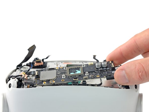
- Use a spudger to pry up and separate the motherboard from the headset.
- If it feels like the motherboard is caught on something, check that all the cables are disconnected from it.
- Remove the motherboard.
- You can reuse the thermal paste if you keep it clean. Otherwise, use a spudger to scrape off the old paste and apply a small amount of thermal putty or viscous thermal compound (such as K5 Pro) to the processor.
- Use your fingers or tweezers to peel and remove the two camera covers from the top cameras.
- During reassembly, align the cutouts on the camera covers to their respective pegs on the headset.
- The camera covers have different alignment cutouts and aren't interchangeable.
- Peel and remove the black tape covering the antenna cable.
- Set this tape aside to be reused during reassembly.
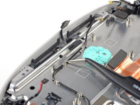
- Use tweezers to lift and unclip the black antenna cable from the metal grounding clips.
- Use a spudger to pry up the black lock tab securing the left microphone flex cable to the left interconnect cable.
- Use your fingers or tweezers to slide the microphone cable out of the ZIF connector.
- Repeat the procedure to disconnect the right microphone cable.
- Slide the point of an opening pick underneath the battery flex cable to loosen the adhesive securing it from the headset.
- Some interconnect cables have been removed in the following images for clarity purposes. You don't have to remove them as part of the procedure.
- Use a Phillips screwdriver to remove the four screws securing the screen and lens assembly to the frame:
- Two 6.5 mm‑long screws
- Two 7.7 mm‑long screws
- Grasp the screen and lens assembly with your fingers.
- Slowly lift and separate the assembly from the outer shell, taking care to reposition any cables that get in the way.
- Remove the screen and lens assembly.
- During reassembly, be careful not to trap the twelve cables as you insert the lens assembly into the outer shell:
- Three cables along the top edge—two flex cables and one LED flex cable
- Two cables in the top right corner—the battery connector and an antenna cable
- Two cables along the right edge—an antenna cable and a wide flex cable
- Two flex cables along the bottom edge
- Three cables along the left edge—one antenna cable, one flex cable, and one speaker cable
- You can use a rubber band to help secure the cables out of the way.
- Use a Phillips screwdriver to remove the two 4.5 mm‑long screws securing the power button and LED board to the outer shell.
- Use your fingers or tweezers to remove the power button and LED board.
- During reassembly, align the board using the two alignment pegs. The pegs have different diameters, so the board will align in only one orientation.