Meta Quest 2 Controller Vibration Motor Replacement
ID: 169178
Description: This guide shows how to remove and replace the...
Steps:
- Use your fingers to slide the battery cover down towards the strap end of the controller.
- Remove the battery cover.
- If you're taking the controller apart for repairs, remove the batteries in the controller.
- Use your fingers to grasp the wrist strap near the anchor peg.
- Lift the wrist strap anchor peg straight out of its recess.
- Remove the wrist strap.
- Heat an iOpener and apply it to the bottom edge of the controller faceplate for a minute.
- The controller faceplate is secured with adhesive and three friction pegs.
- Press the edge of an opening tool into the seam between the controller faceplate and shell, near the Oculus button.
- If you can’t get the opening tool into the seam, heat the area with an iOpener for a minute and try again.
- Slide the opening tool to the base of the ring shell to loosen the adhesive.
- Use an opening tool to pry up on the seam to loosen the first friction peg.
- Continue prying around the entire faceplate to separate the remaining friction pegs and adhesive.
- If you're having trouble, apply a heated iOpener to the faceplate for a minute and try again.
- Remove the controller faceplate.
- The three friction pegs should hold the faceplate securely, so you don’t need to replace the adhesive during reassembly. Be sure to firmly press the faceplate onto the controller so that all friction pegs fully engage.
- Use a Torx T5 driver to remove the four screws securing the controller ring shell to the controller:
- Two 4.7 mm‑long screws
- Two 5.9 mm‑long screws
- Press the point of a spudger firmly against the white alignment square to release the ring shell.
- Use your fingers to grab the end of the ring shell that doesn’t have the white alignment square.
- Gently lift the ring shell up and away from the controller to unclip it from the controller.
- Remove the controller ring shell.
- Use a Torx T5 driver to remove the five screws:
- One 11.5 mm‑long screw
- Three 5.9 mm‑long screws
- One 18.2 mm‑long screw
- Use tweezers and your fingers to peel the battery information label out from the battery compartment.
- If you want to reuse this sticker, be careful not to tear it. If it’s difficult to peel, apply a heated iOpener to it for a minute to soften the label adhesive.
- Use a Torx T5 driver to remove the four 5.9 mm‑long screws securing the side shell to the controller:
- Three screws inside the battery compartment
- One screw near the corner of the battery compartment
- Pull the bottom of the side shell slightly away from the controller to loosen the shell.
- You may hear a few clicks as the clips release. This is normal.
- Part of the side shell is looped around a screw post. In this step, you’ll spread the screw post apart enough to slip the shell out.
- Insert the flat end of a spudger into the gap between the controller ring and the front shell.
- The front shell is the plastic frame part below the front trigger.
- Twist the spudger to widen the gap between the front shell and the controller.
- Position the spudger so that it can stay in place without you holding the tool.
- Guide the looped part of the side shell through the screw post gap.
- Remove the side shell.
- During reassembly:
- Spread the screw post wide enough to loop the side shell back around it.
- Be careful not to pinch the antenna cable or the tracking flex cable as you reposition the side shell.
- Use tweezers or your fingernail to pull the vibration motor connector out of its socket.
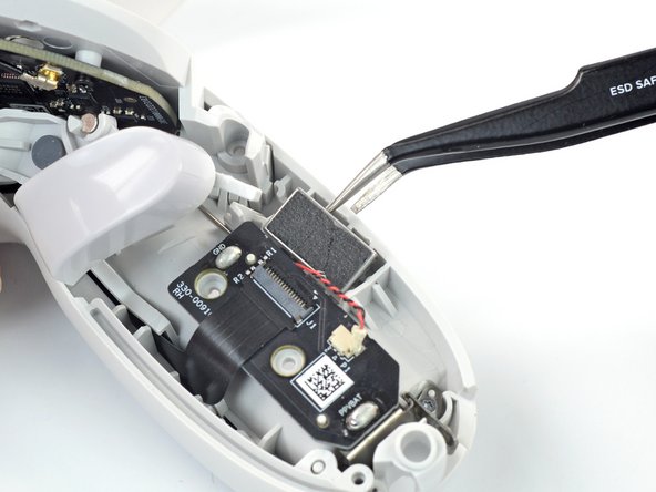
- Insert one arm of a pair of tweezers between the vibration motor and the controller.
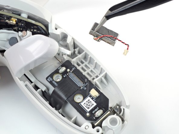
- Pry to loosen the vibration motor.
- Remove the vibration motor.
- The vibration motor is held in place mostly by a friction fit. If your motor feels loose when you replace it, secure it in place with some double-sided tape.