Hitron CODA Teardown
ID: 169712
Description: Product Number 1504300014V0
Steps:
- Remove rubber covers first. Attached with some weak glue, they are relatively easy to pry away. Only the 2 at the back of the device have screws underneath.
- Use a screwdriver to remove the screws.
- Plastic tabs line the case where the upper and lower halves meet.
- I found it easiest to start prying from the sides of the back.
- Keep prying until the case is fully separated and the top half lifts up/forwards.
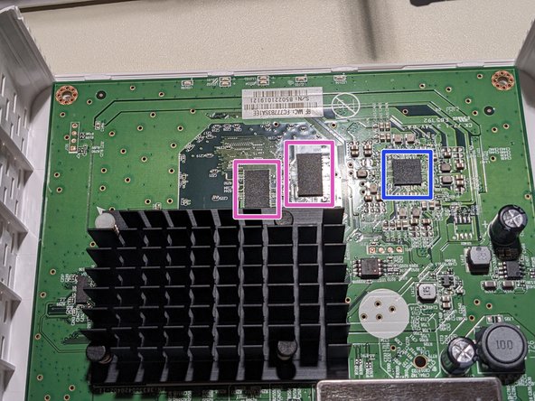
- Ethernet switch: Realtek RTL8363SC sibling datasheet 1, sibling datasheet 2, programming guide
- Ethernet magnetics: Bothhand/Pulse Electronics LG2P109RN datasheet
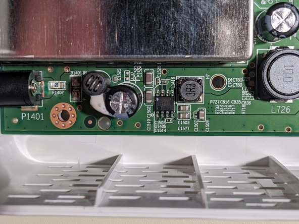
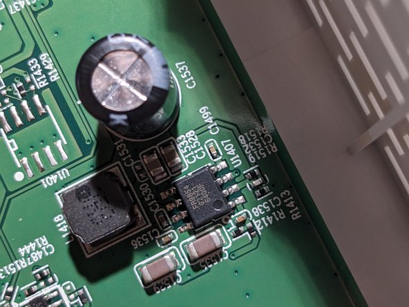
- Step-down converters (2x): Fitipower FR9854 datasheet
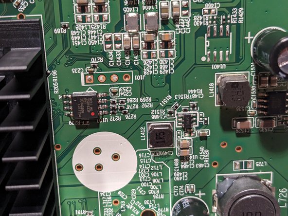
- Serial NOR SPI flash (16Mb): Macronix MX25U1633FM2I datasheet, flash dump
- eMMC: Phison PS8211-0 details 1, details 2, details 3
- LED driver: Rohm BD2651MWV sibling datasheet 1
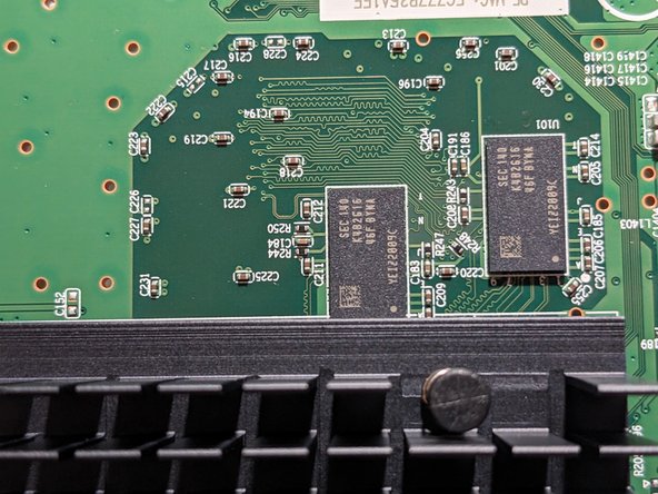
- DRAM (2x 2Gb): Samsung K4B2G1646F-BYMA datasheet, product page
- Be careful, yanking too hard can damage/disconnect the processor.
- Squeeze the tip of the heatsink legs (e.g. with pliers) so you can pull them back through the PCB holes.
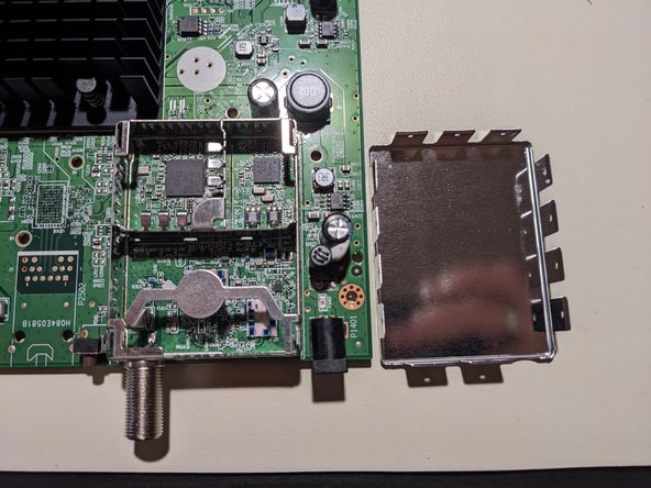
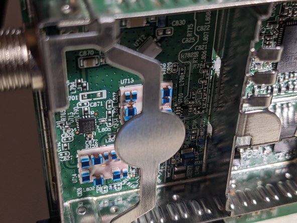
- Pry up the tabs around the edge of the shield.
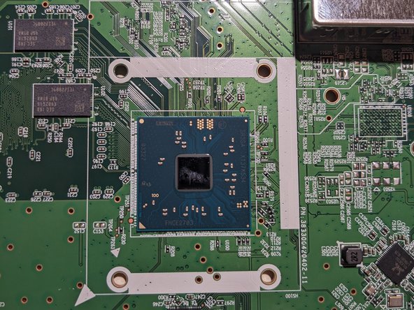
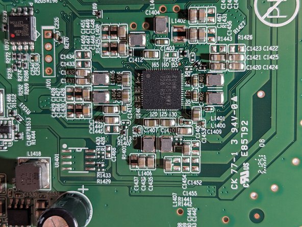
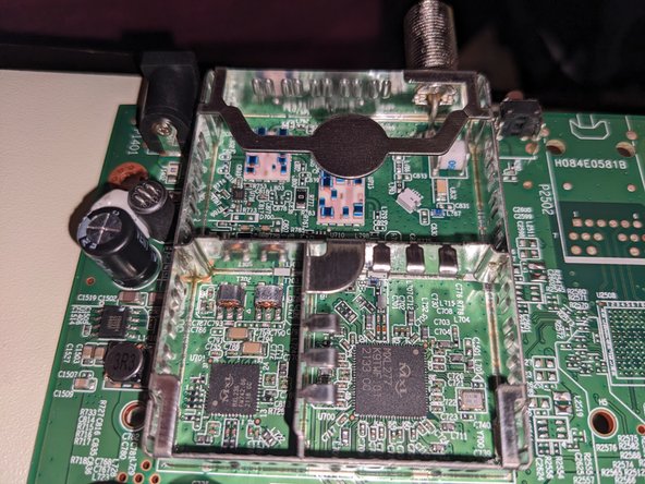
- SoC: Intel FHCE2703 SR3SA (Puma 7) related products
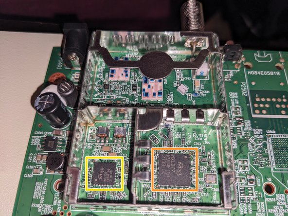
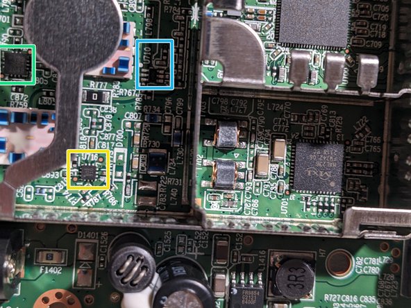
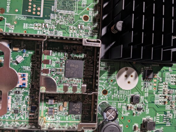
- DOCSIS cable tuner: MaxLinear MxL277 product page
- DOCSIS upstream amplifier: MaxLinear MxL 236 product page
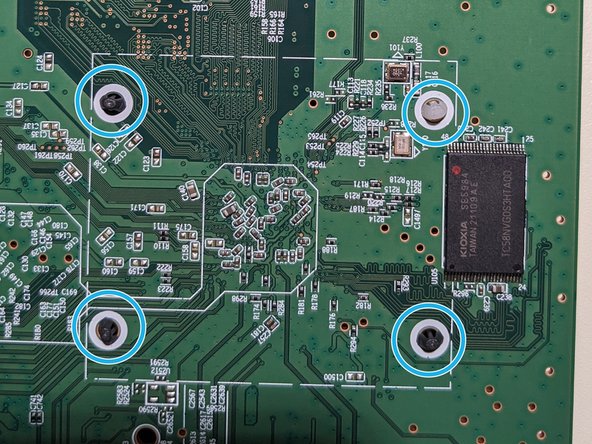
- Use a screwdriver to remove the screws.
- Lift the PCB away from the case.
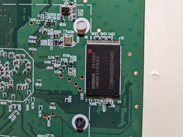
- Serial NAND EEPROM (1Gb): Kioxia TC58NVG0S3HTA00 datasheet
- Debug headers factory firmware bootlog
- Once you plug in your modem to the cable network, your ISP will update the firmware to a version that has features for, and is tested to be compatible with, their network (it's part of the DOCSIS spec, specifically the "SwUpgradeFilename" option in the config file. See here for details).
- My modem, once it upgraded to the Xfinity firmware, no longer shares its bootlog to UART on either debug header (as verified with a logic analyzer, both attached and unattached to the cable network).
- There is a silkscreen arrow pointing to one pin on each of the debug headers. The pin on the opposite end, farthest away from the arrow, is ground.
- Product number 383300420402-11
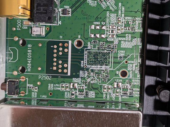
- Unpopulated connector H084E0581B
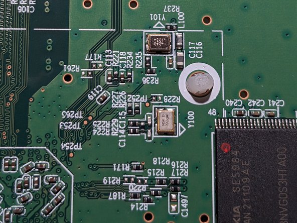
- Various test points (labeled "TPXXX")
- 602 910
- V39 3601 2049
- U710
- Insert wisdom here.
- Insert wisdom here.
- Insert wisdom here.
- Insert wisdom here.
- Insert wisdom here.
- Insert wisdom here.