Ventilation Plate Removal
ID: 169765
Description: Prereq for removing the ventilation plate with...
Steps:
- Unplug all cables and fully shut down your laptop.
- If your repair requires a spudger, a T5 Torx, or a Phillips screwdriver, you can use the included Framework screwdriver. Whichever works best for you!
- Use your fingers to slide the touchpad spacer toward the bottom edge of the laptop and unclip it.
- If you're having trouble, check if the corresponding Input Module latch is properly unlocked.
- Lift the touchpad spacer off the laptop and remove it.
- Repeat the same procedure for the other touchpad spacer.
- Use your fingers to slide the touchpad toward the bottom edge of the laptop and disconnect it.
- If you're having trouble, check if the Input Module latches are properly unlocked.
- Lift the touchpad and remove it.
- During reassembly, perform the following:
- Place the touchpad flat on its cutout so its clips are properly aligned.
- Press the touchpad down and slide it into place so it lines up evenly with the bottom edge of the laptop.
- The keyboard is held in place with strong magnets. Apply gradually increasing force to avoid having the keyboard violently eject.
- Grip the two pull tabs along the bottom of the keyboard.
- Lift the pull tabs until the keyboard magnets release.
- Remove the keyboard.
- During reassembly, make sure the keyboard is seated properly on its alignment pegs and sits evenly with the edges of the laptop.
- The numpad is held in place with strong magnets. Apply gradually increasing force to avoid having the numpad violently eject.
- Grip the pull tab at the bottom of the numpad.
- Lift the pull tab until the numpad magnets release.
- Remove the numpad.
- During reassembly, make sure the numpad is seated properly on its alignment pegs and sits flush with the edges of the laptop.
- Grip the black pull tab on the midframe cable press connector.
- Lift up to disconnect the midframe cable.
- The midframe screws are ordered from 2–17 (number 1 is the press connector). You don't have to follow the order, but you can use it to help keep track of the screws you've loosened.
- Use a T5 Torx screwdriver to loosen the 16 captive screws securing the midframe.
- During reassembly, follow the order (starting with 2) to reinstall the screws across the midframe evenly.
- Use your fingernail to lift the bottom edge of the midframe enough to grip it with your fingers.
- Lift the midframe off the laptop and remove it.
- During reassembly, make sure the midframe sits evenly on its alignment pegs before tightening the screws.
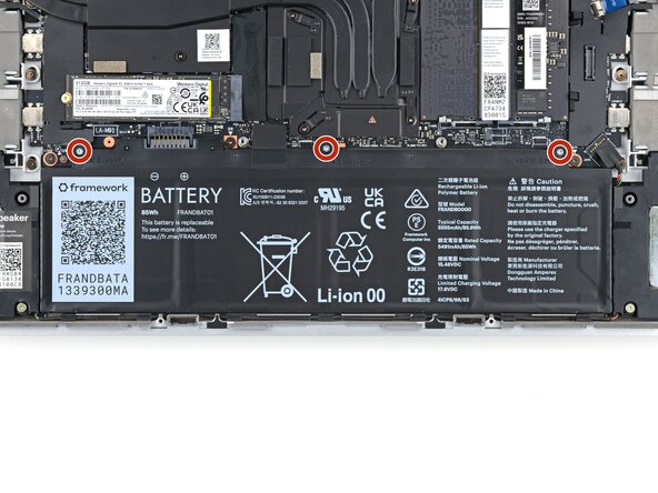
- Use a T5 Torx screwdriver to loosen the three captive screws securing the battery.
- Grip the black pull tab at the top of the battery.
- Lift the pull tab to disconnect the battery connector.
- Remove the battery.
- Lift the interposer door by its black pull tab and let it rest upright.
- If you have the graphics module installed, your interposer will have four screws. Otherwise, you'll have three screws.
- Lift the pull tab on the interposer and let it rest vertically to access all of its screws.
- Use a T5 Torx screwdriver to loosen the three captive screws securing the interposer.
- If you have the graphics module, use a T5 Torx screwdriver to loosen the four captive screws securing the interposer.
- Lift the interposer by its pull tab and remove it.
- Use a T5 Torx screwdriver to loosen the two captive screws securing the expansion bay.
- Close the interposer door before continuing.
- Slide the Expansion Bay module out of the laptop and remove it.
- The module should slide out easily. If you feel any resistance, check if the screws holding it in place are fully loosened.
- Use the flat end of a spudger, or a clean fingernail, to lift up the locking tab on the fingerprint sensor ZIF connector.
- Use tweezers, or your fingers, to grip the blue pull tab and slide the fingerprint sensor cable straight out of its socket.
- The fingerprint sensor cable is lightly adhered to the laptop frame.
- Use your fingers to peel the fingerprint sensor cable away from the frame and separate the adhesive.
- During reassembly, if your adhesive is still sticky, press the cable to the frame to re-adhere it. Otherwise, use double-sided tape to replace the adhesive.
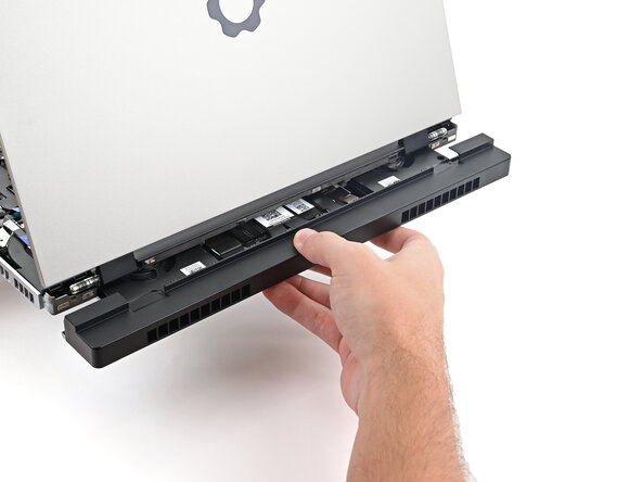
- The ventilation plate is held in place with magnets.
- Lift the bottom of the ventilation plate and pull it away from the laptop until the magnets release.
- Remove the ventilation plate.