Coffee De'Longhi EN95.R Button light left on or won’t turn on.
ID: 170711
Description:
Steps:
- Cafetera Delonghi EN95. R, pushing down the on button, the two green lid lights are dim. Pay attention as this data is important, if it has these problems, it may be caused by a fault of the condenser which is the purpose of this report.
- If the machine doesn’t turn on at all, it may be a problem caused by the thermal fuse located in the boiler, either one of them or both, or a fault in the cables, or failure of the condenser which can also be found in this report, from these two problems, the first thing to do is measure the voltage of red electric of the PCB.
- For the second problem of the machine where the light won’t turn on, take a look at this other guide. I dedicate this to the next videos which I leave here: https://www.youtube.com/watch?v=fG6cx7K_... iFixit Precision 4 mm Screwdriver Bit
- https://www.youtube.com/watch?v=3o4zjSCO...
- SUMMARY: CAFETERA NESPRESSO Takes time to heat up or button remains flashing dim lights. In this guide I will focus on how to change the condenser of 680 mf/275V which affects both the button and heating for the water in the boiler.
- We remove the 2 screws Torx which hold the PCB, We remove the lid of the plate, and gain access to the condenser, lying down, next to the plate, we pry it off to unstick. To substitute the condenser, do not make it complicated. All that is needed is to cut the terminal in a L angle and solder the replacement in the same place. Quick and Easy
- In case we want to measure before changing, we will cut only one leg or terminal to separate it from the PCB and measure, Change the condenser. We need to test the machine out. If the machine remains unresponsive it must have a burned resistor of 150 ohms 2W or one of the two thermofuse located in the boiler.
- Guide for prerequisites to demonstrate this case: https://es.ifixit.com/Gu%C3%ADa/Cafetera...
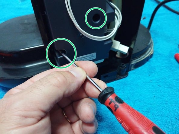
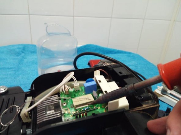
- We remove the case on the right with a screwdriver TORX T9, We begin to see the two screws which connect the electronic module to the chassis.
- For better work it’s recommended to lay the machine down.
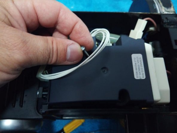
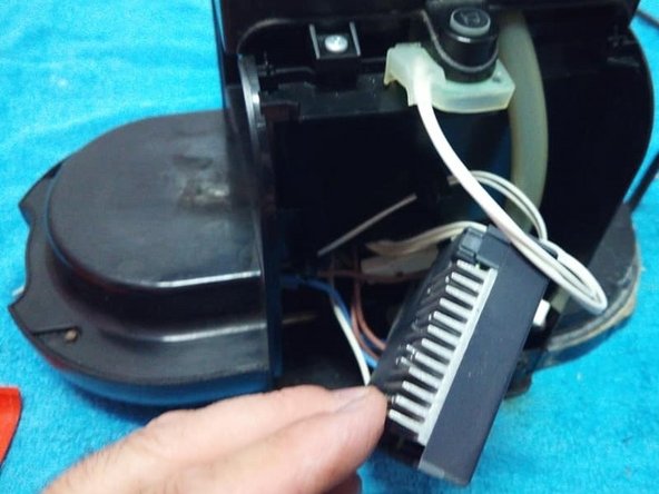
- We extract the electronic module and open up the lid.
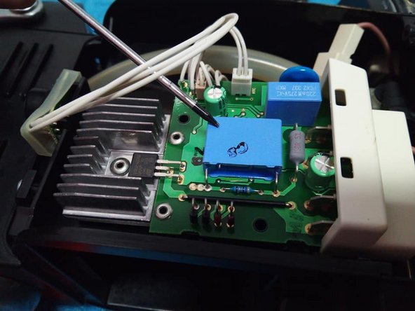
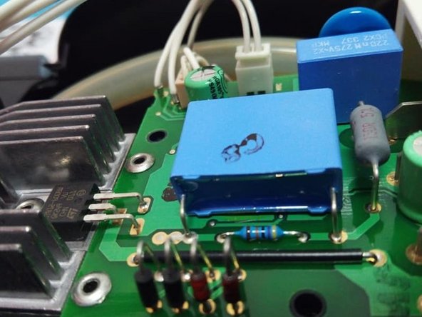
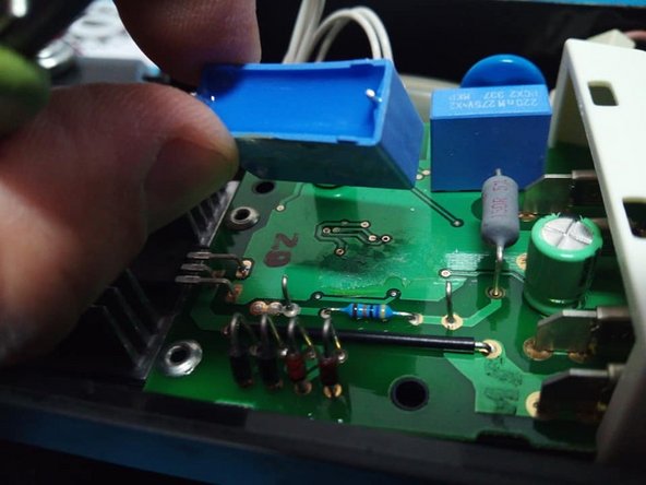
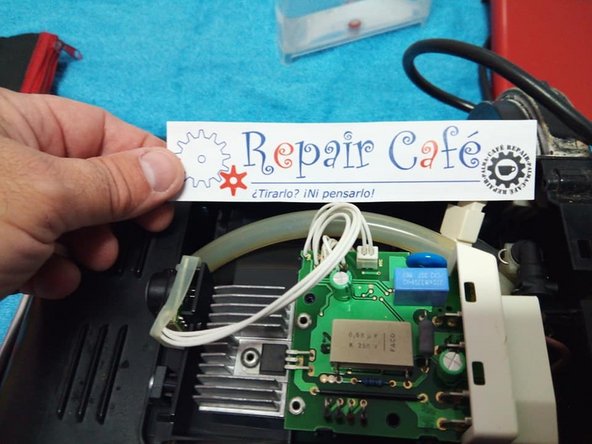
- Here we have the PCB in sight, our problem in 95% of cases is that the buttons are turned on, the fault is located in the center of the condenser, the one bigger in size.
- The same problem can be seen in more older versions, in a horizontal format which is easily shown and substituted “resoldering the original terminals”.
- 680 nF/ 275 V condenser view
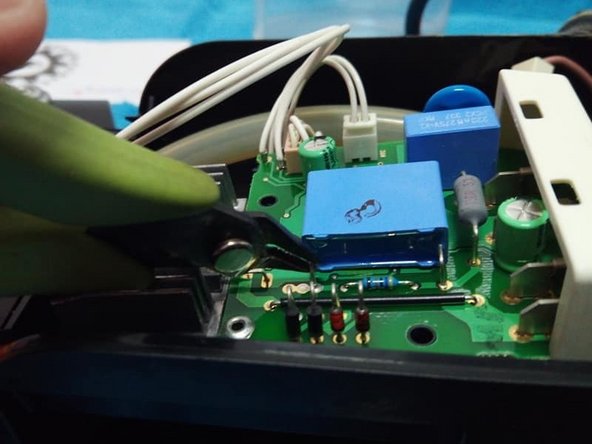
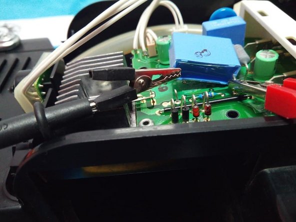
- With some cutting pliers, we cut one of its pins or terminals to be able to measure it without removing it from the PCB entirely. Remember that a capacitance meter can only measure it by itself, not when it is directly in the PCB
- If you don’t have a capacitance meter, you would have to directly replace it, explained in step 9
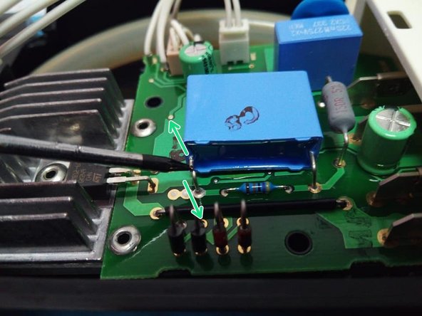
- To come up with the measurement, we slightly separate the condenser from the PCB and short circuit its terminals with a pair of scissors and a screwdriver BEFORE we measure it, so we don’t damage the measuring apparatus with residual voltage
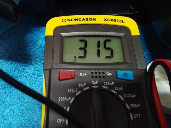
- Testing with a capacitance meter, a 680 nF condenser measures 315 nF in this case. Clearly, it is faulty, under capacity, and it must be replaced.
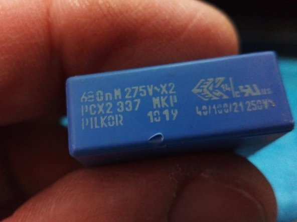
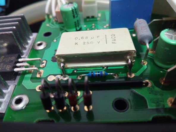
- Notice that the damaged component is screen printed with the following IMPORTANT information:
- 680 nF capacity
- Maximum work voltage: 275 V
- Condenser model: MKP information is also important, the replacement also needs to be an MKP, a type of build more adequate for condensers directly fed by an electrical network
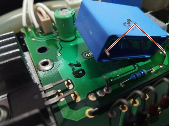
- Confirming that it is damaged, we proceed to replace it. We will cut the other terminal of the condenser
- We discard the condenser
- ALWAYS test the replacement, especially if it is recycled or reused from another PCB.
- And very recommended to test it, even if the replacement is new, given that we can get surprises from new components, low on capacity.
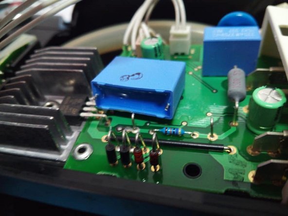
- We position the condenser on the plate and carry out 2 air solderings to unite the 2 condenser pins with the 2 condenser terminals from previously.
- This repair method may appear questionable, given that you would rather use a new condenser with long terminals and solder directly to the PCB, however, this method is effective, just as valid, saves time and avoids complications.
- Once you’ve replaced the condenser, lift the machine, connect the network cable and check if the buttons light up bright green. Machine repaired.
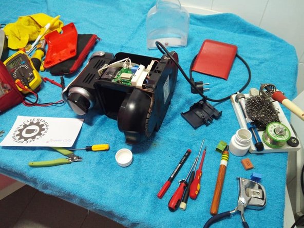
- View of some of the tools used.
- This is just an exhibit, as general culture, if the problem is not solved replacing the large 680 nF condenser, replace in 2º the small one, and if the problem persists, the last option is the 3º electrolytic, but I don’t think it will come to this.
- At last, position the PCB in its location, take the cover and screw it on
- A few years ago I have made several videos about this repair on youtube: https://www.youtube.com/watch?v=ZCz1RJKB...
- https://www.youtube.com/watch?v=THMaT8rs...
- https://www.youtube.com/watch?v=RfENhqfe...
- The value of the capacitor can vary from one model of machine to another, in this other one for example it was 470 nF https://www.youtube.com/watch?v=xkANvzIb...
- END of the guide.