Motorola G30 screen replacement
ID: 170809
Description: Guide to replace a broken screen on Moto G30...
Steps:
- Remove the SIM card tray with a pin or a small pointy object
- Unclip the plastic back cover using any tool you like (mediators, sprudgers, Jimmy...)
- Be careful not to lift the cover too far from the phone, it has to be lifted cautiously because a cable is attached to it
- Slighly move the back cover in order to unscrew the plastic piece behind it
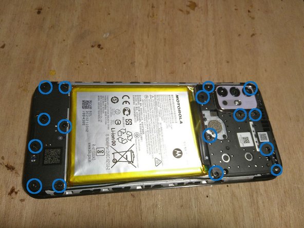
- Remove the 9 small Philips-head screws inside
- You will also have to remove small black adhesive pieces to be able to remove the part completely
- Once the black plastic cover piece is removed, unplug the cable holding the back panel
- Once this flex cable unplugged, lift the back panel completely
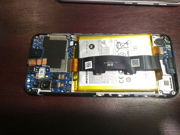
- Unplug both battery and display connectors
- Battery on the right
- Display in the middle
- You can use the opening tool as lever.
- Very carefully unglue the battery
- Adhesive is quite strong here, and the battery is not very rigid, so this is a complicated operation. It would be dangerous to head the battery cell, be patient and careful.
- Unscrew the cover at the bottom of the phone
- 7 small Philips head screws to remove
- A little black adhesive to peel off around the edges
- Unplug the connector
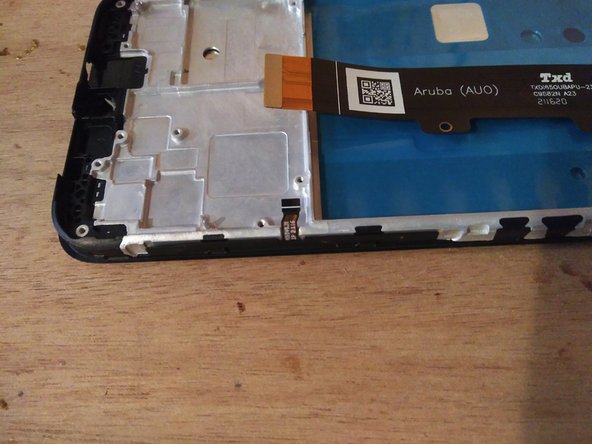
- Detach the display flex cable from the back of the chassis
- Steps 9 and 10 are only useful if you order the display without its frame. Move on to step 11 if you intend to order the display with its frame
- Heat up to help unglue the screen
- Battery has to be removed first, heating batteries is dangerous
- Unglue the display from the chassis
- I could not properly unglue with a cutter blade on the side. My technique is simpler and more brutal: I pushed the display away from the connector hole, with a rigid tool.
- Remove the glass shards still glued around the frame
- Put some gloves on, because glass shards are dangerous!
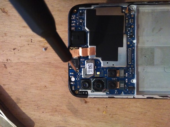
- Replug the battery pack
- Test the battery voltage on the test point to the left of the connector (the ground is everywhere on the metal chassis): it must be between 3.6 and 4.2 V
- You can also test the motherboard with a Linux-based computer
- Unglue the screen-USB-motherboard flex cable from your broken screen, and replug the bottom USB board with the top motherboard
- Turn on phone with Power On + Up buttons
- Plug it to the computer with an USB-C cable
- Type "lsusb" in a shell
- If you can read something like "22b8:XXXX Motorola PCS moto g(30)", congratulations: your motherboard still lives
- Once your phone has been successfully torn down and tested, it is time to order the replacement screen
- The part will cost you around 15-20€. You can find it here for instance
- Two choices: ordering the display pre-assembled on a new frame, or ordering it without
- I recommend pre-assembled display, it will be more sturdy and less subject to breaking
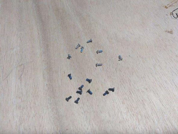
- While waiting for your order, don’t forget to store your parts and small screw properly
- If you ordered the display pre-assembled on a frame, you will have to move all the components from the old chassis to the new one
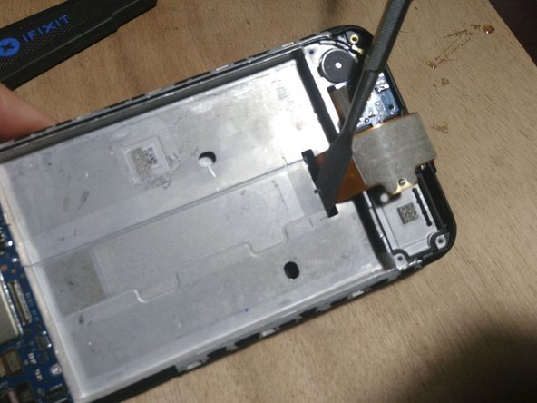
- You will find the small button panel on the chassis side, unglue it carefully
- Start by ungluing the black tape covering it
- Unplug the button connector from the main PCB
- Unglue the button flex board carefully
- Glue it on the new chassis
- Unscrew both PCB
- The top one is held by 2 screws
- The bottom one is help by one screw
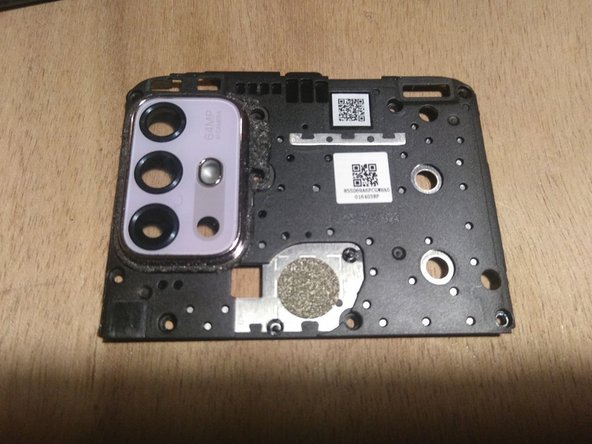
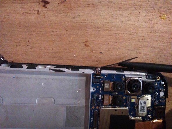
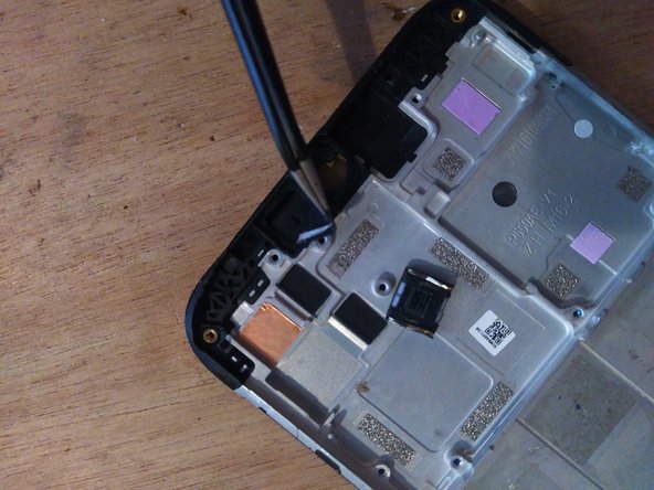
- Slide the top PCB out of the chassis
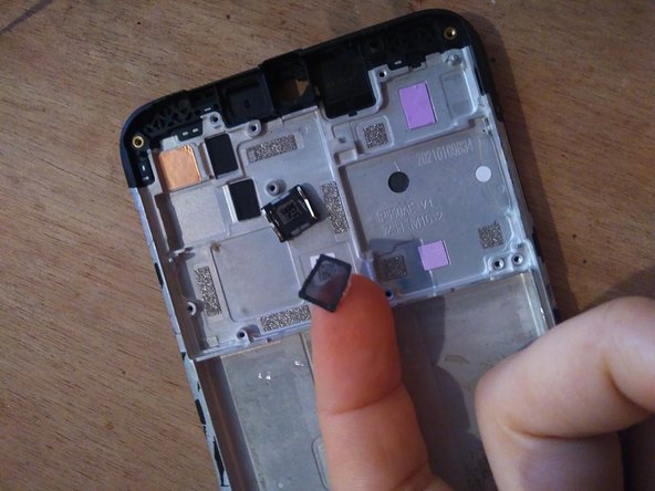
- Under it, there is a small undefined module, and an opaque sticker
- Get the module out of its casing
- Unglue the sticker under it
- Replace both module and sticker on the other side
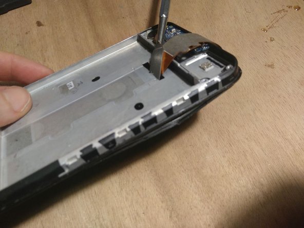
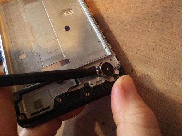
- Remove the bottom PCB
- The haptic module is under it, unglue it carefully
- Start by the connector side
- Once the connector side is lifted, it is easier to get to the rest of the module and unglue it
- Try to salvage the stickers and glue them back to the new frame
- You can also use new stickers
- The pink sticker is a very thin thermal pad, you can replace it by thermal paste
- The orange sticker is a tape copper foil
- I don’t know how to replace the metallic grey thing, it is probably use for a better RF shielding
- Insert the top PCB into the new frame
- Don’t forget to move the button PCB small connector out of the way, it could get stuck under the board
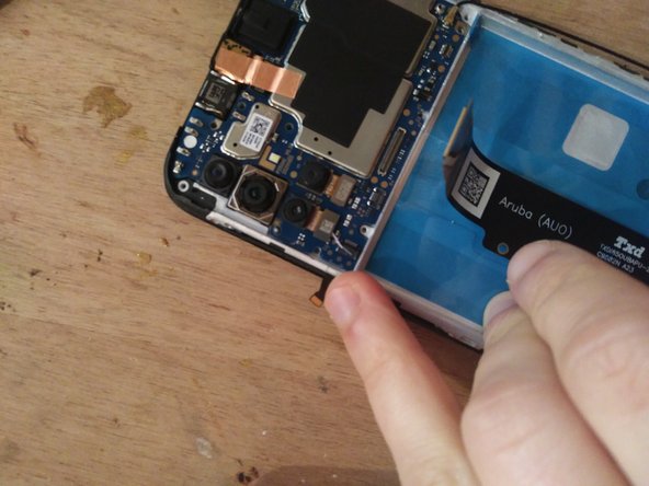
- Plug the elements back
- Top and bottom screen module connectors
- Right-side antenna cable
- Small button PCB connector
- Screw the boards back in place
- Replug the back cover connector
- A step you don’t see on the pictures because I forgot
- Rescrew the two PCB covers
- Clip the cover back in place
- Insert the SIM card holder