Ryobi P517 Motor Replacement
ID: 170921
Description: Use this guide to remove and replace the motor...
Steps:
- Position the saw so you can access the button-clips on both sides of the battery.
- Press and hold the button-clip on both sides and take the battery out.
- Lay the saw flat so the left side is facing up.
- Remove the grey orbital button by twisting it counterclockwise.
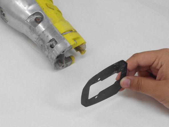
- Remove the rubber boot from the device by peeling it from back to front.
- Flip the saw so its right side is facing up.
- Remove the 10 mm screw using a Torx T27H screwdriver.
- Grab the black shoe assembly and pull it out from the front of the saw.
- Remove the two 12.5 mm screws from the front of the guide plate using the Torx T10H screwdriver.
- Then remove the guide plate.
- Flip the saw so its right side is facing up.
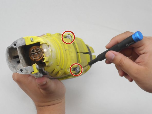
- Use the Torx T15H screwdriver to remove the eleven 18.1 mm screws from the housing assembly.
- Refer to the diagram provided to identify the gear case.
- Use a Torx T15H screwdriver to remove the four 30.7 mm screws that are holding the housing assembly with the gear case assembly and gear case cover.
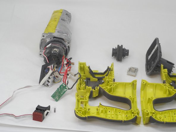
- Pull apart the two sides of the housing.
- If the housing assembly does not come apart easily, do not try to force the pieces apart or else you may damage it. Ensure that all screws have been removed.
- Refer to the diagram on the device page to locate the trigger-switch, circuit board, and contact plate assembly. Each of these parts is connected by wires.
- Remove the switch, circuit board, and contact plate holder assembly from the housing assembly.
- Gently remove the switch by taking out the wiring from the assembly. Rough handling of the wiring could damage it and require it to be replaced.
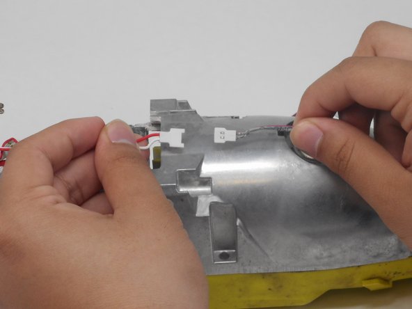
- Lift and remove the gear case from the housing assembly and ensure that there are no parts remaining in housing assembly.
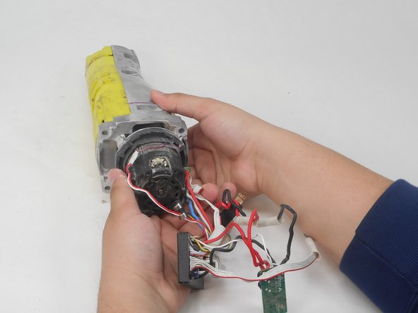
- Ensuring the motor remains attached to the gear case to ease reassembly.
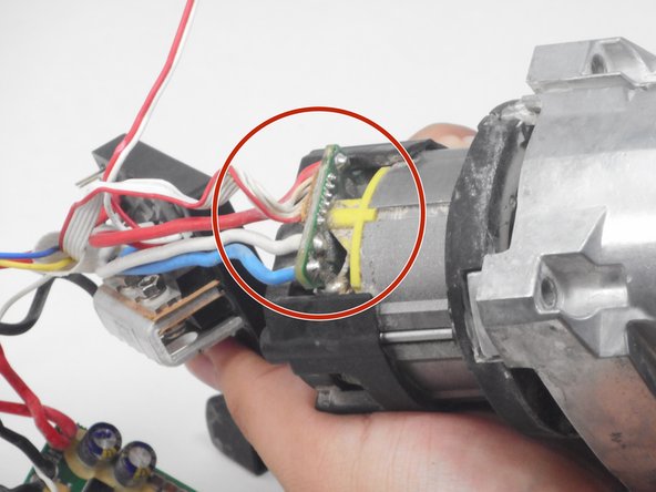
- Position the saw so the ports connecting the circuit board assembly to the motor are accessible.
- Use the soldering iron and desoldering pump to desolder the circuit board assembly from the motor.
- Be extremely careful with soldering iron. Improper use of the iron could damage the device and could lead to bodily harm.
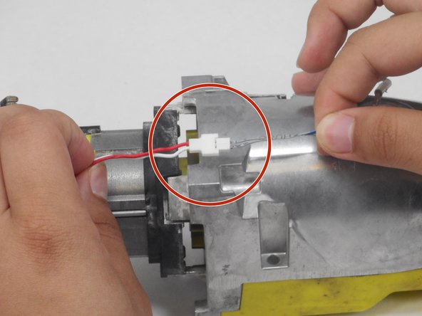
- Gently pull the thin red and white wire on opposite ends of its connector to disconnect the LED from the circuit board.
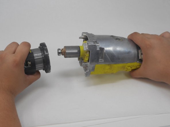
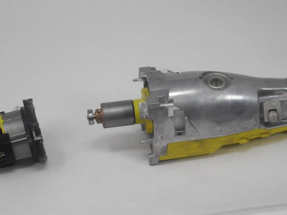
- Firmly grasp the motor in one hand while holding the gear case in your opposite hand.
- Disconnect the motor from the gear case by firmly pulling the two pieces apart.