Aorus FV43U Power Supply Replacement
ID: 171047
Description: Follow this guide to replace the internal power...
Steps:
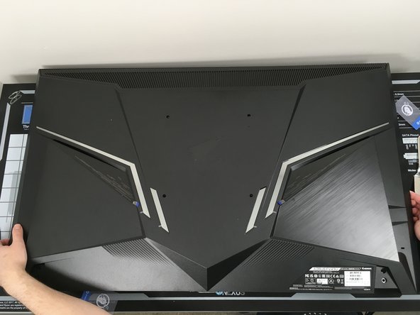
- Unplug all cords from your monitor. Place your monitor face-down on a flat, non-slip surface, ensuring there is nothing on the surface which could scratch your monitor.
- A clean project mat or non-slip pad would be ideal for this since the monitor will likely move around from the significant force required to remove the back panel.
- Note: It is highly recommended to leave your monitor unplugged for a significant amount of time before working on the internals. The internal power supply is exposed and bridging the contacts on its circuitry could result in serious injury or death. If you leave it unplugged and are careful to only handle it by the edges, you should be safe.
- If you are using the included feet or VESA mounting hardware, those need to be removed. This typically involves unscrewing 4 screws using a Phillips #2 head screwdriver, but may vary if you have a specialized mount.
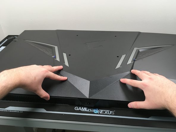
- To replace most of the components of the FV43U, you must enter from the back. The back panel is held in place entirely with plastic clips rather than screws.
- Undoing these plastic clips takes significant force. Take your time and work carefully.
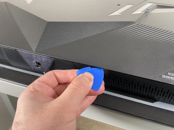
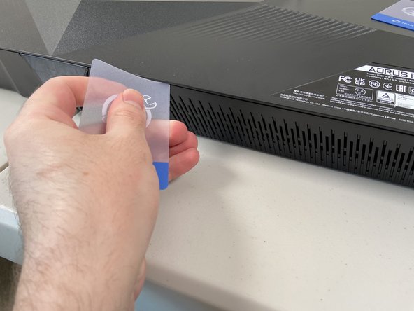
- Plastic tools like iFixit Opening Picks and Plastic Cards are not strong enough to undo these clips and are not recommended for this process.
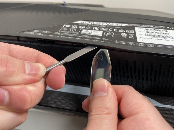
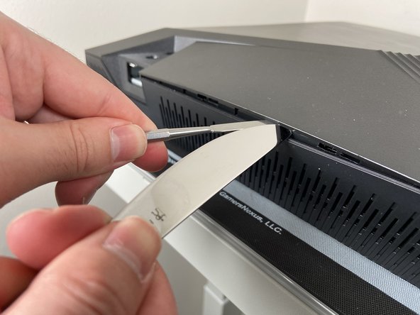
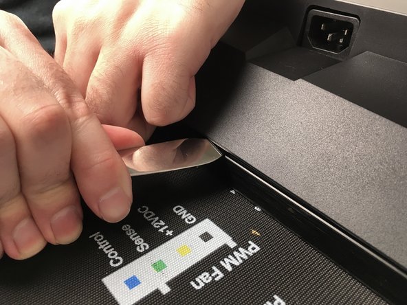
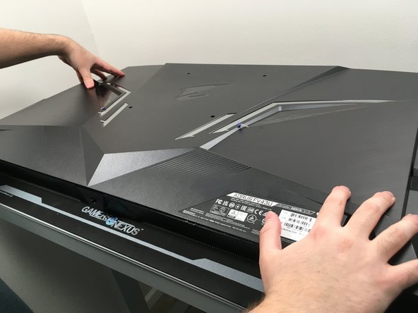
- To pry open the panel, use dull metal prying tools such as a non-serrated butter knife or a Metal Spudger. Using two of these tools in tandem will give you the best leverage to avoid bending or breaking the plastic.
- Start at the bottom under the model sticker. Insert your tools about 1/4" (~6.5mm). Use one to lift the back and turn the other gently until each clip "pops" itself out. Make sure you can get a good grip on your tools to avoid slipping, it does take significant force to open.
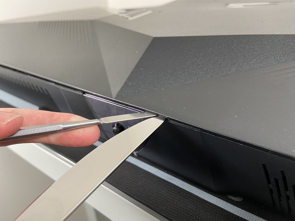
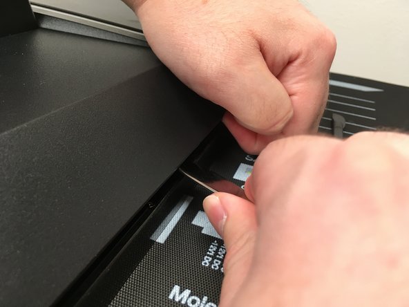
- Work your way from here outwards to the sides. Be especially careful around the on-screen display (OSD) controls in the center. Do not pry directly above the joystick.
- For this entire process your tools never need to go deeper than 1/4" (~6.5mm).
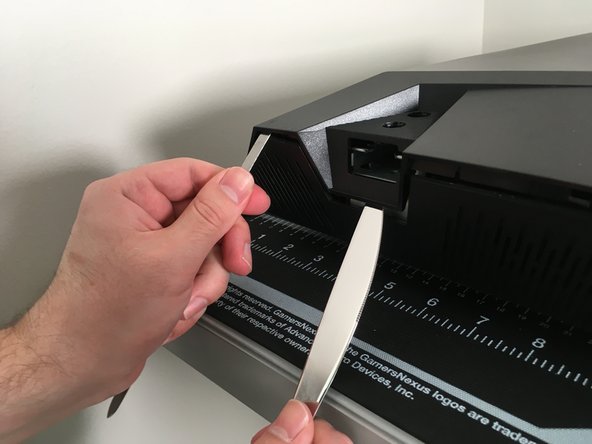
- Once the bottom portion is free, begin prying up the corners. Use the area beneath the stand to gain leverage, and you should feel the side start to pop out as well.
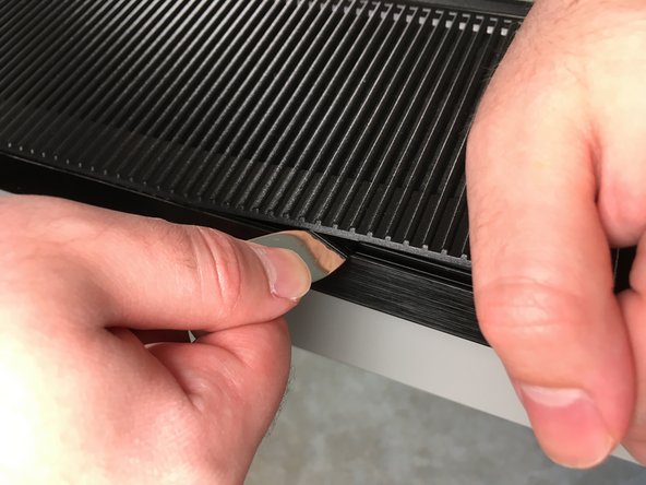
- Avoid using the speaker grilles as leverage. They are the weakest points of the monitor body.
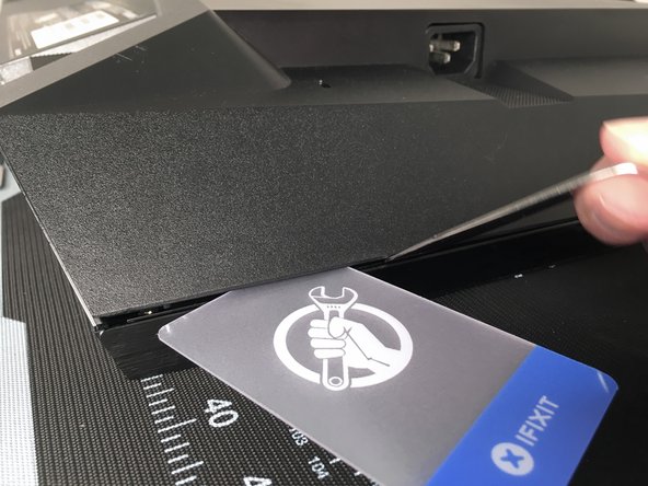
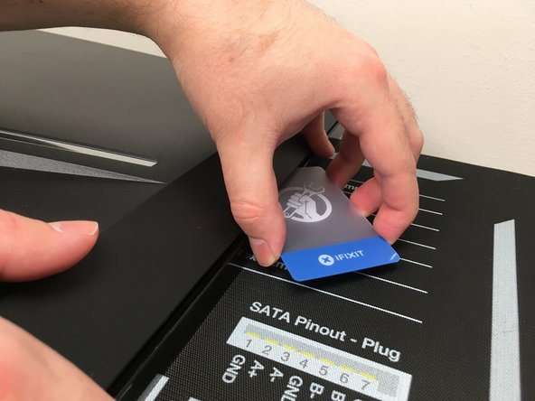
- Insert a Plastic Card to keep one side open while you work on the other side. The force exerted on one can inadvertently re-fasten the clips on the other.
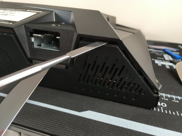
- Use your prying tool to work your way up the side of the display. Be careful not to insert your tool deeper than 1/4" (~6.5mm) or use the bezel as too much of a brace.
- Once again use Plastic Cards to prevent the clips from re-fastening. Make sure both sides are free before prying open the top.
- Unfastening the top is as simple as the sides - insert your prying tool about 1/4" (~6.5mm) and turn it gently until each clip "pops" itself out.
- Once the panel is unfastened, do not immediately remove it. A delicate speaker cable is still connecting the back panel to the motherboard on the display.
- Gently lift the back panel from the bottom. Only lift as far as needed to access the speaker connector.
- Disconnect the speaker cable by grasping its connector on both sides and gently pulling it straight out.
- Always disconnect a cable by pulling on its connector, not the wire itself.
- Tip: Most of the cable connectors in this monitor have a ridge on the back of them. Use your fingernails to grab this ridge during removal.
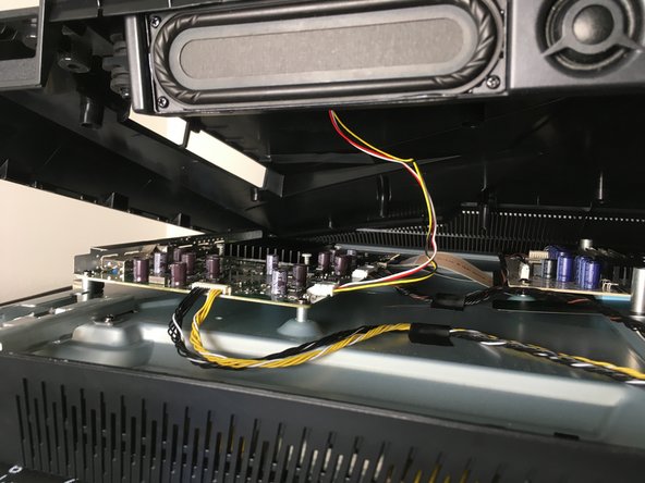
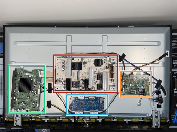
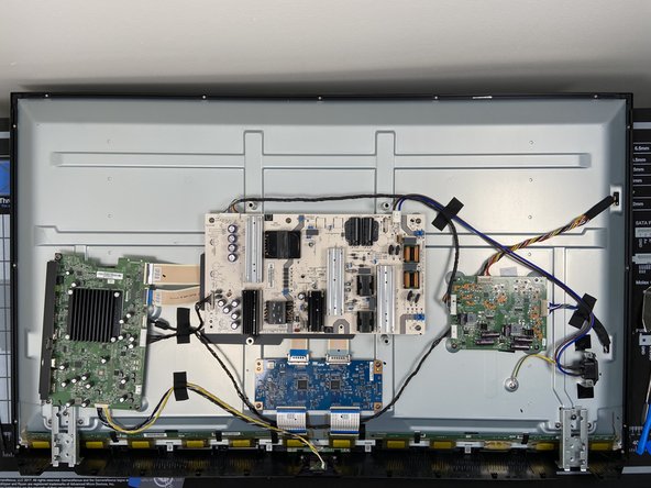
- With the speaker cable disconnected, lift the back panel up and out from the monitor. This gives us a good look inside.
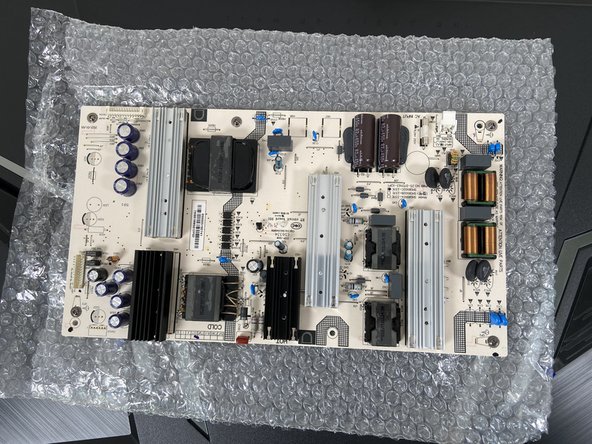
- Power Supply - this is what we're replacing. These are sometimes external power bricks but are often internal like this one. Since it is uncovered, be very careful not to touch any of its components or solder joints.
- Motherboard - this includes all the inputs and outputs for our display.
- T-Con (Timing Controller) board
- LED Driver board
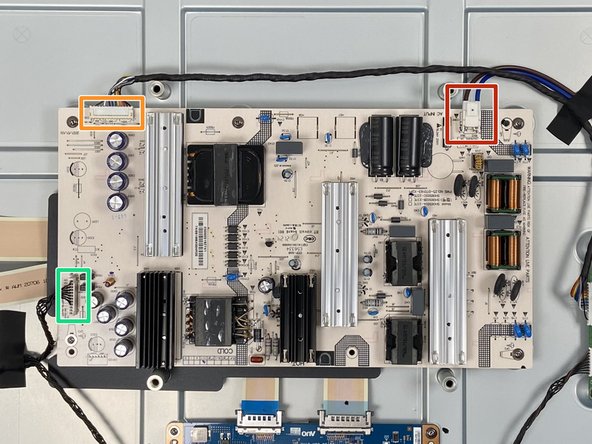
- There are three cables you'll need to disconnect from the power supply:
- AC inlet power cable connector
- Motherboard power cable connector
- LED Driver power cable connector
- Note: Do not touch any components on the power supply. Only handle the power supply by the edges where there are no components or soldering joints on either side. Even while unplugged, power supplies hold significant charge in their capacitors and being electrocuted by them could result in serious injury or death.
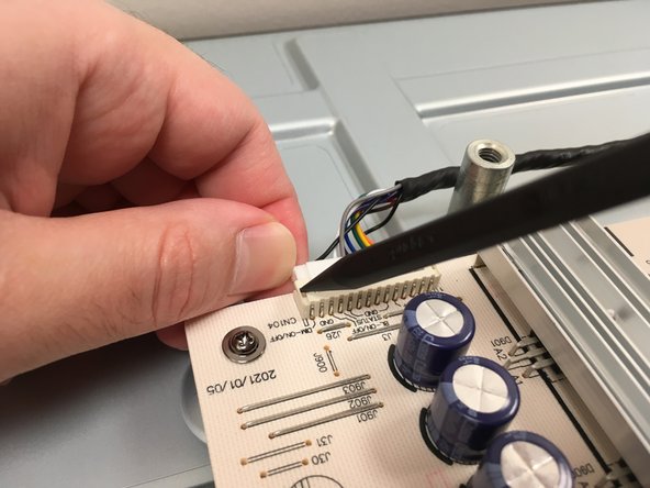
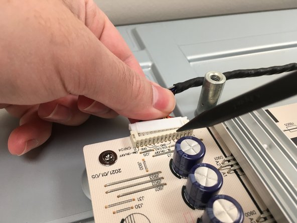
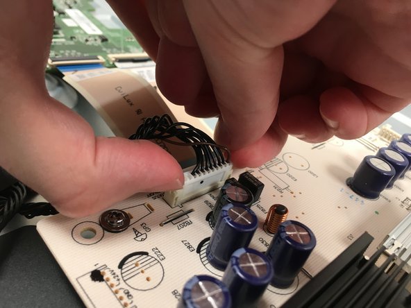
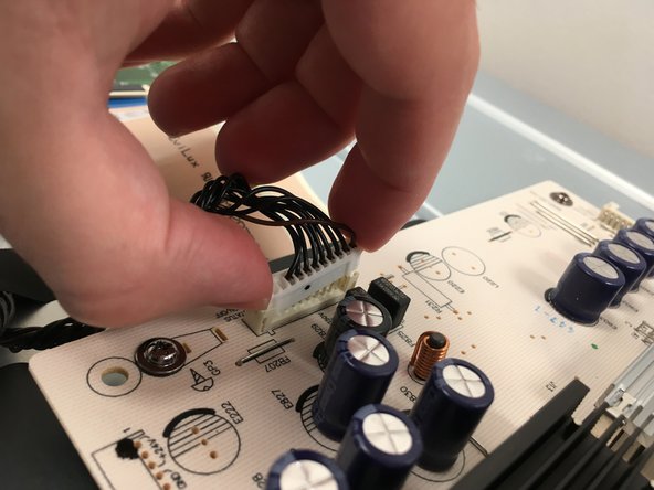
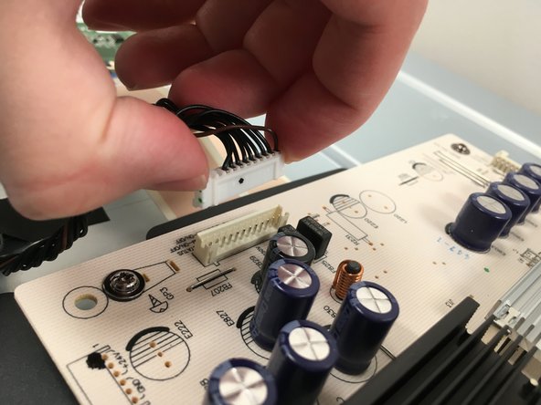
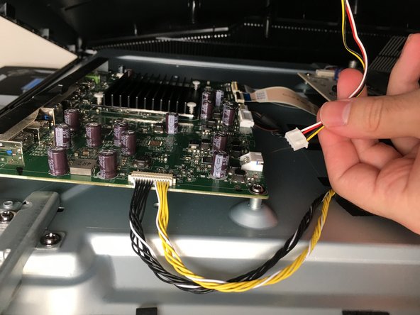
- Disconnect the bundled power cable for the LED panel. Use a finger and the sharp end of a Spudger or toothpick to push out the corners of the connector. Only pull on the wires themselves once the connector is loose. Pulling too hard could damage them.
- Pull evenly on the full width of the cable so that no individual wires are overly strained.
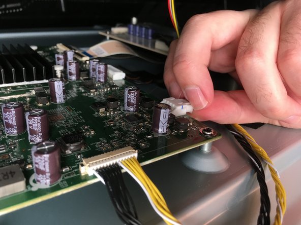
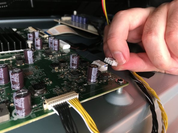
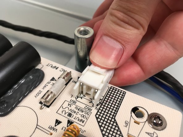
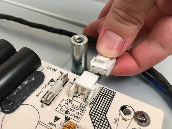
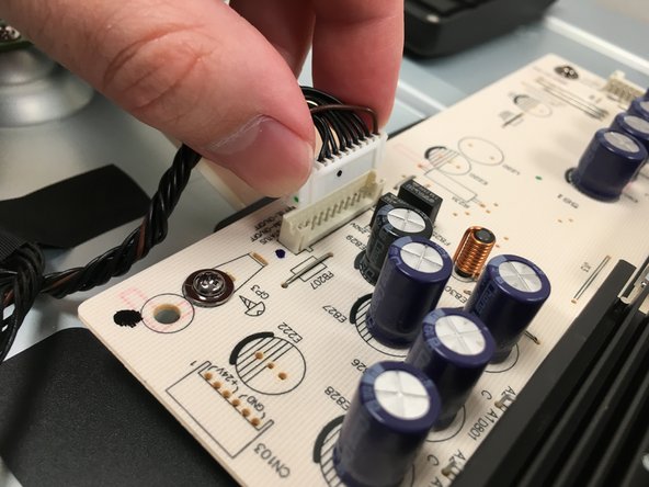
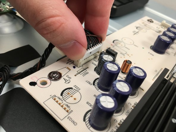
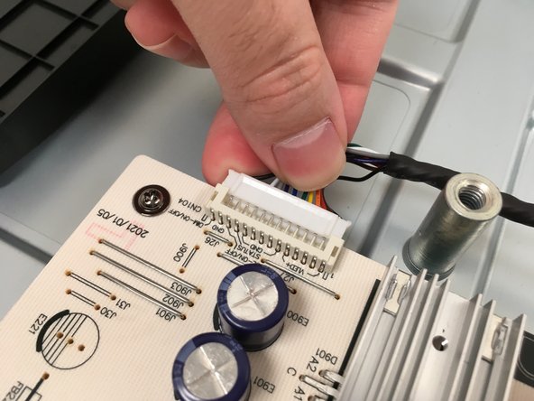
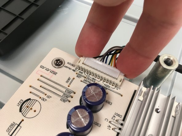
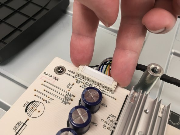
- Pull firmly on one side of the motherboard cable connector to loosen it and then pull the entire thing out. It may require "walking" it back and forth by pulling one side and then the other until it is free.
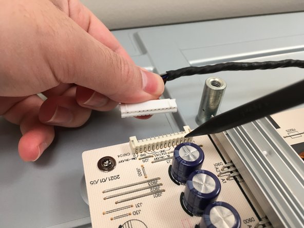
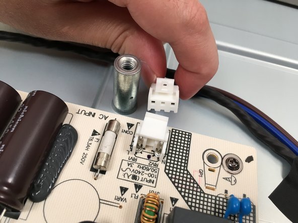
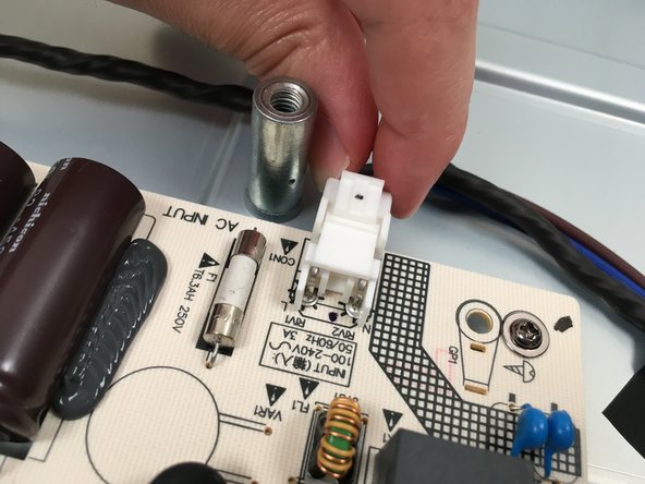
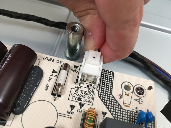
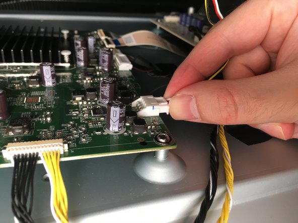
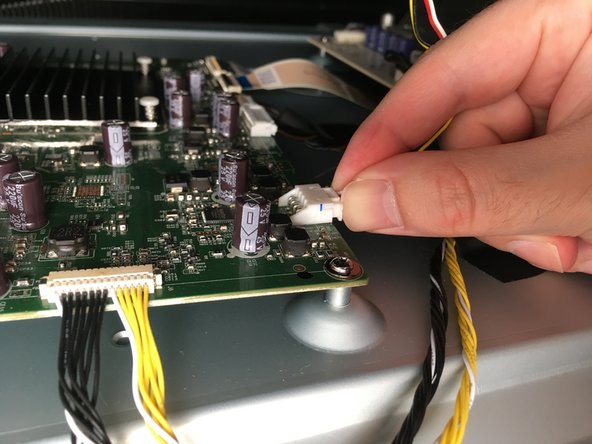
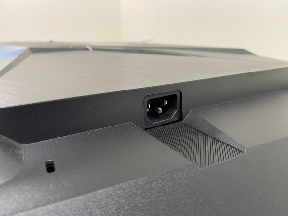
- To disconnect the AC inlet cable, squeeze the clip on the connector housing and pull it straight out.
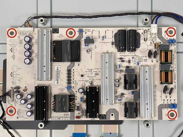
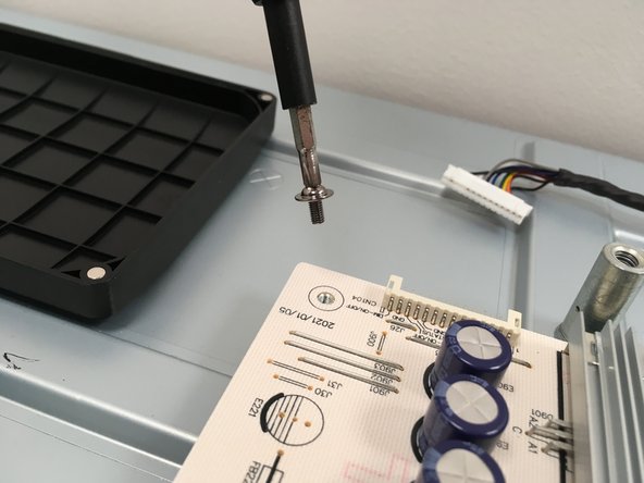
- Use a Phillips #2 head screwdriver to unscrew all five 8mm screws located around the edges of the power supply.
- Be extremely careful not to touch any of the circuitry with your screwdriver. Doing so could result in sparks or electrocution.
- Tip: While all these screws are identical, it's a good practice to place them in an organized parts tray in the shape they came out.
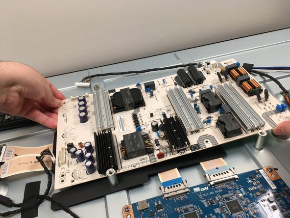
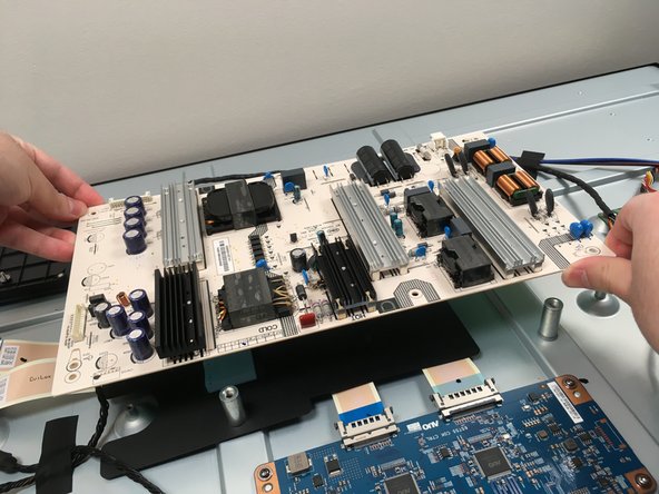
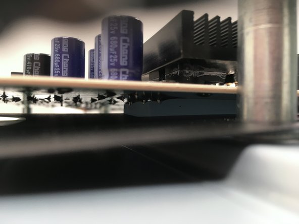
- Remember to always hold the power supply by the edges where there are no components or soldering joints on either side.
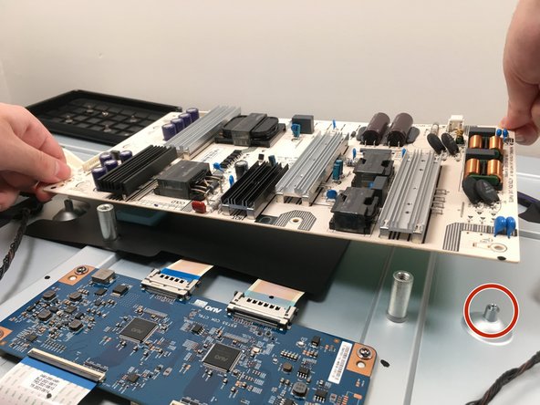
- The power supply will feel "stuck" to the monitor due to its thermal pad. Steadily but firmly lift the power supply straight out by the edges.
- If the thermal pad comes up with the power supply, put it back where it was to ensure the new unit is properly cooled.
- Note: Only handle the power supply by the edges where there are no components or soldering joints on either side. Even from the factory, power supplies can hold significant charge in their capacitors and being electrocuted by them could result in serious injury or death.
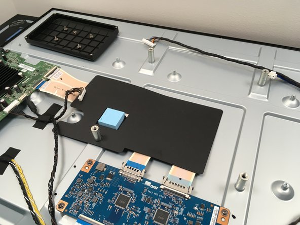
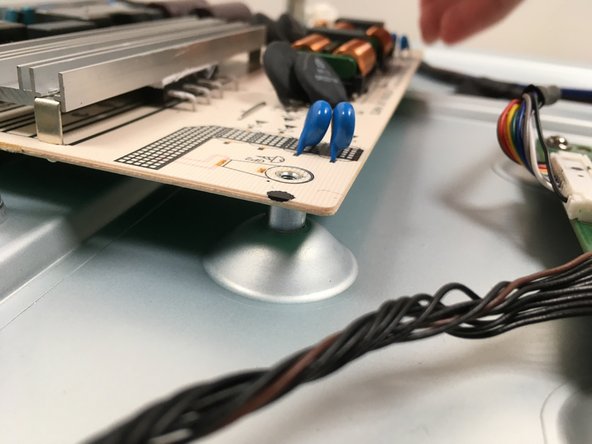
- The bottom-right stand-off has a built-in nub for the power supply to rest on. Align the new power supply on this nub first.
- Once it has been properly aligned, place it all the way down while making sure all five screw holes are aligned.
- Reminder: the power supply will stick to the thermal pad underneath. Make sure the new power supply is aligned with the screw holes before it sticks to the pad.
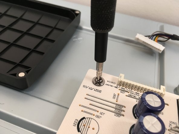
- Use a Phillips #2 head screwdriver to screw the new power supply in using the five 8mm screws removed in Step 16.
- To ensure proper alignment, fasten them in diagonal order. i.e. top left, then bottom right, etc.
- Double-check that the thermal pad is making contact with the bottom of the new power supply.
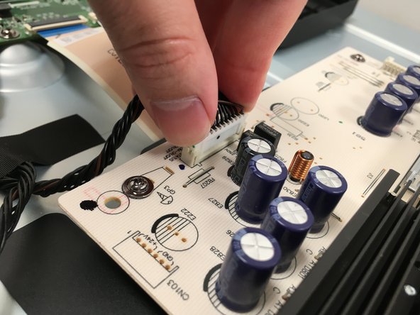
- Once the new power supply has been screwed in, reconnect the motherboard cable.
- Ensure the connector is aligned, place it in the receptacle, and gently but firmly push down on both sides of the connector until fully seated.
- Use the tips of your fingers to push on the solid plastic connector and not the wires.
- Align the LED cable connector with its port, then place a finger on either side and gently push until fully seated.
- Lastly, connect the AC inlet cable to its connector. Align, push, click - done.
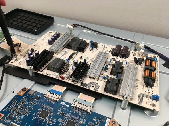
- This is what your internals should look like. Exactly the same as before, but with a new power supply.
- Do not plug the monitor into the wall with the back panel removed. The power supply is entirely exposed and accidentally touching it (especially when plugged in) could result in serious injury or death.
- Insert the back panel into the top of the monitor, then lower it until you can plug the speaker connector back in.
- Gently insert the speaker cable connector into its receptacle and push evenly on it until fully seated.
- Do not plug in the monitor without installing the back panel. The power supply is entirely exposed and accidentally touching it (especially when plugged in) could result in serious injury or death.
- Align the back panel by inserting it flush at the top, then gently lowering it down until it settles into place.
- It is recommended to test the monitor with the back panel aligned but not fully re-latched. The feet can be installed without re-latching the clips. That way, if the new power supply does not fix the problem, you won't have to un-fasten all those clips again.
- To fully re-latch the back panel, work backwards from the way you took it off. Firmly but evenly push down starting at the top and work your way down the sides. Finally, go across the bottom until everything looks flush.