PlayStation Portal Grip Shell (Left) Replacement
ID: 172097
Description: This guide shows how to remove and replace the...
Steps:
- Before you begin repairs, power off your PlayStation Portal and unplug any cables.
- Both bumpers are held in place with clips.
- Rest a finger over the L1 bumper to prevent it from flying off when you pry.
- Insert the flat end of a spudger between the top edge of the bumper and the white shell.
- Pry up to unclip the bumper.
- Slide the spudger along the seam to release any remaining clips.
- Remove the L1 bumper.
- Repeat the procedure to pry up and remove the R1 bumper.
- To install a bumper during reassembly:
- Align the bumper into its slot.
- Use a finger to press the bumper down firmly until it clicks into place.
- Insert the tip of an opening pick underneath the left joystick trim strip, where it wraps below the grip.
- Twist the opening pick to release the bottom clip.
- Insert the tip of an opening pick underneath the outer edge of the trim strip.
- Slide the opening pick along the edge to release the clips.
- Insert the tip of an opening pick under the inner edge of the strip.
- Slide the opening pick along the edge to release the clips.
- Grasp the bottom edge of the trim strip and slowly lift to release any remaining clips.
- If the strip feels stuck, twist or shift the strip sideways to help release any stubborn clips.
- Lift and remove the left joystick trim strip.
- Repeat the procedure to unclip and remove the right joystick trim strip.
- To reattach a trim strip during reassembly:
- Use your fingers to align and clip the top edge in place.
- Firmly press along the remaining edges to clip the strip in place.
- Use a Phillips screwdriver to remove the two 6.5 mm‑long screws at the bottom tips of each grip.
- You may need to peel off some tamper-evident stickers to access the screws.
- Use a Phillips screwdriver to remove the two 6.5 mm‑long screws securing the top corners of the shell.
- The back shell is still secured with numerous clips. The next few steps will show how to unclip the shell while reducing the chance of damaging the clips.
- Push the flat edge of a spudger into the back shell's left, inner seam.
- This releases the clip in that area while flexing the shell slightly, creating a larger outer seam.
- Keep the spudger inserted in the seam.
- Insert the tip of an opening pick into the shell's left, outer seam.
- Slide the pick along the seam to release the clips securing the edge.
- Keep a pick in the seam to prevent the shell from clipping back together.
- Remove the spudger from the inner seam.
- Repeat the previous three steps on the right side of the Portal to release the clips along the right edge.
- Carefully flip your Portal over.
- Grasp the top edge of the back shell, near a corner.
- Gently pull the top edge away until you feel the clips release in that corner.
- Pull along the top edge to release all the top edge clips.
- Grasp the bottom edge of the back shell, near the center.
- Pull away with firm force to release the clips securing the bottom edge.
- Remove the back shell.
- To clip the back shell in place during reassembly:
- Align the corners near the trigger buttons first.
- Firmly press around the entire perimeter to clip the shell back in place.
- Use a Phillips screwdriver to remove the two 6.5 mm‑long screws securing the left grip shell to the Portal.
- From the back, these screws are on the right side of the Portal.
- These screws can be tight. Brace the Portal with your hand and apply strong pressure to the screwdriver.
- You can also try using a JIS #00 screwdriver to get a better grip on these screws.
- Grasp the top edge of the grip shell and twist it slightly outwards (away from the screen) to release the inner clips.
- Insert the flat edge of a spudger underneath the inner edge of the grip shell, near the vibration motor.
- Twist the spudger along the edge to unclip the bottom portion of the grip shell.
- Remove the left grip shell.
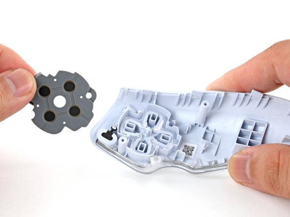
- Use your fingers to peel the gray button cover away from the grip shell and remove it.
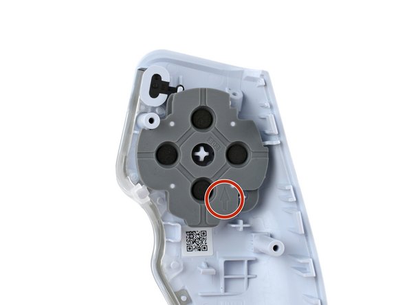
- During reassembly:
- Make sure the orientation arrow on the button cover points upwards.
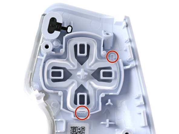
- Flip the grip shell over to drop out the D-pad.
- During reassembly:
- Orient the D-pad such that the alignment tabs rest in the shell's cutouts.
- Use the point of a spudger to pry up the share button from its attachment point.
- Remove the share button.
- During reassembly, use a spudger to gently press the share button's attachment loop back onto its attachment point.
- Only the left grip shell remains.