Lenovo ThinkPad P1 Gen 7 Fans and Heatsink Assembly Replacement
ID: 173509
Description: Follow this guide to replace the fans and...
Steps:
- Shut down your laptop (don't just put it in sleep mode) and disconnect all cables.
- Flip the laptop upside-down, and rotate it so the screen hinge faces towards you.
- Use a Phillips screwdriver to loosen the six captive screws securing the base cover.
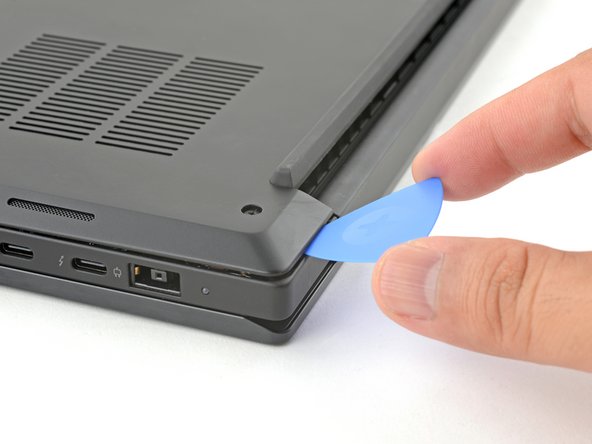
- Press the tip of an opening pick into the seam between the base cover and the bottom-left corner of the frame (near the screen hinge).
- It can be tricky to get the pick into the seam for the first time. Angle the pick vertically and press down with firm pressure.
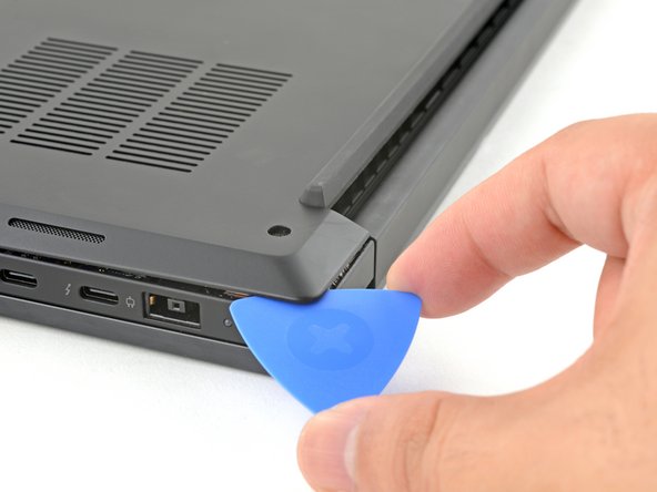
- Pivot the pick down and slide it around the corner to release the clips.
- Slide the opening pick along the left edge to release the clips securing the cover.
- Press the tip of an opening pick into the seam between the base cover and the bottom-right corner of the frame (near the screen hinge).
- Pivot the pick down and slide it around the corner to release the clips.
- Slide the opening pick along the right edge to release the clips securing the cover.
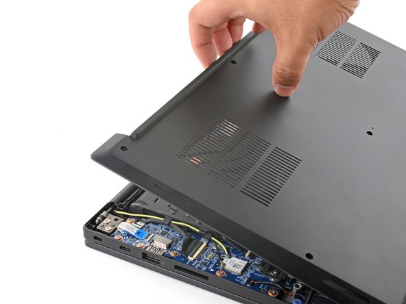
- Grasp the base cover along the screen hinge edge and pull up to loosen the cover.
- Lift and remove the base cover.
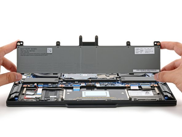
- Because of the battery connector's design, the only way to disconnect the battery is by physically removing it.
- Use a Phillips screwdriver to loosen the six captive screws securing the battery.
- Grasp the top edge of the battery and lift to disconnect it.
- You may feel a little resistance from the battery connector as it disconnects—that's normal.
- Lift and remove the battery.
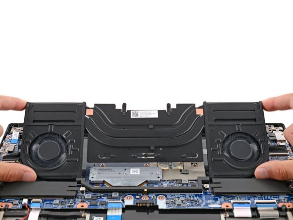
- The fans and heatsink assembly may look slightly different depending on the model. The procedure is nearly identical for both models—any differences will be noted in the relevant steps.
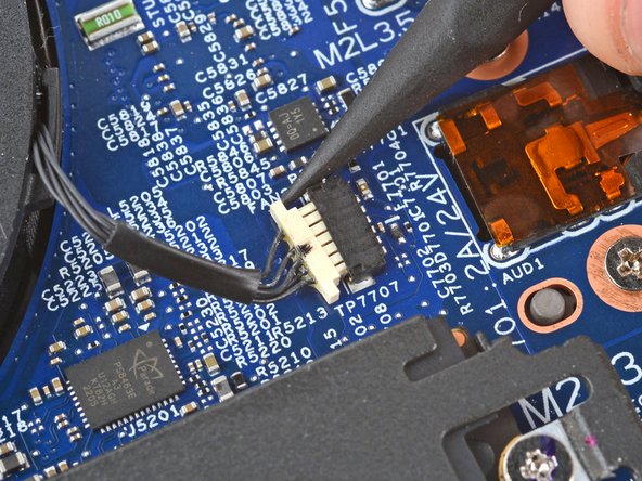
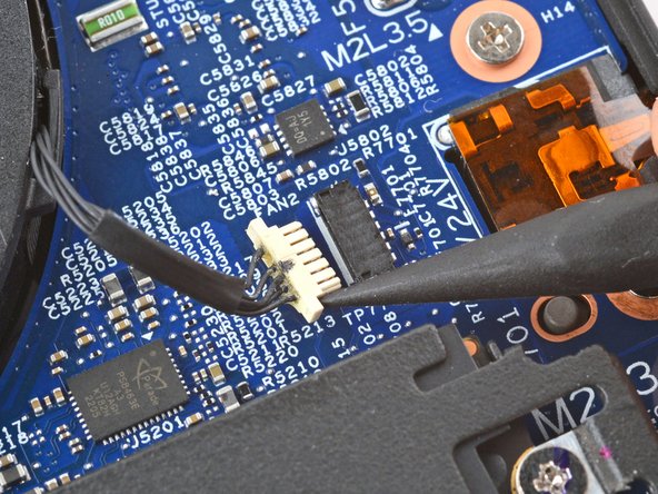
- Use the point of a spudger to push on alternating sides of the fan connector near the right edge and "walk" it out of its socket.
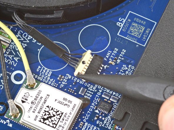
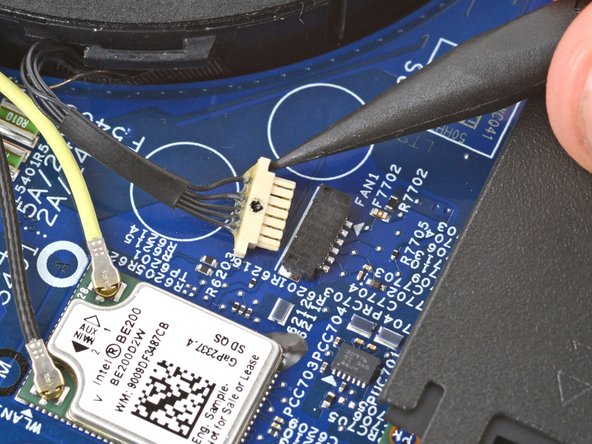
- Use a spudger to walk the fan connector near the left edge out of its socket.
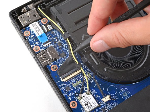
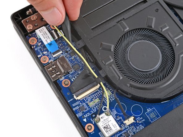
- Use a spudger or your fingers to gently guide the two thinner cables (black and yellow) out of their clips on the edge of the left fan.
- During reassembly, route the two thinner cables and the thicker screen cable into their clips.
- Use a Phillips screwdriver to loosen all captive screws securing the heatsink.
- Depending on the model, your heatsink will have either three or five screws.
- During reassembly, tighten the heatsink screws in ascending order based on the number stamped next to each screw.
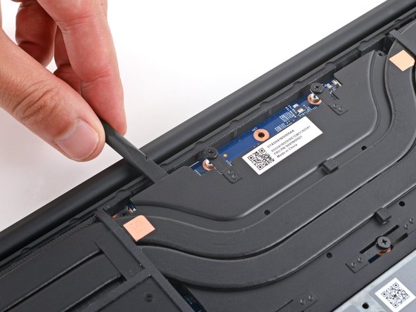
- Insert the flat end of a spudger under the top edge of the heatsink and pry up to separate it.
- Be very careful not to damage any surface-mounted components on the motherboard.
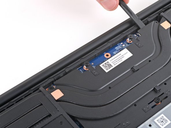
- Continue prying up along the top edge to fully separate the heatsink.
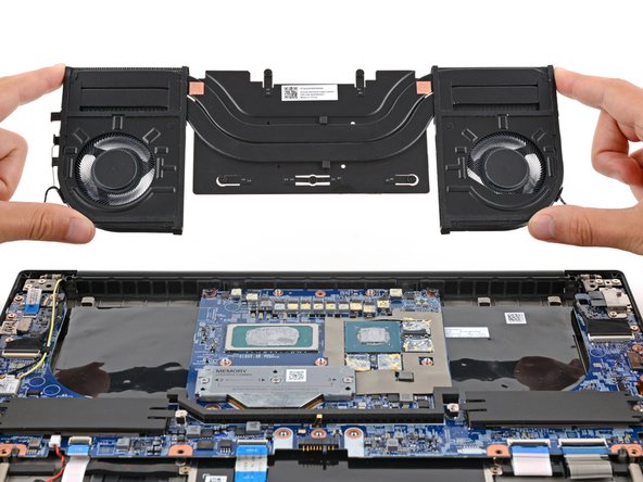
- Grab the outer edges of the fans and remove the assembly.
- Reference our thermal paste guide for cleaning and application during the next two steps.
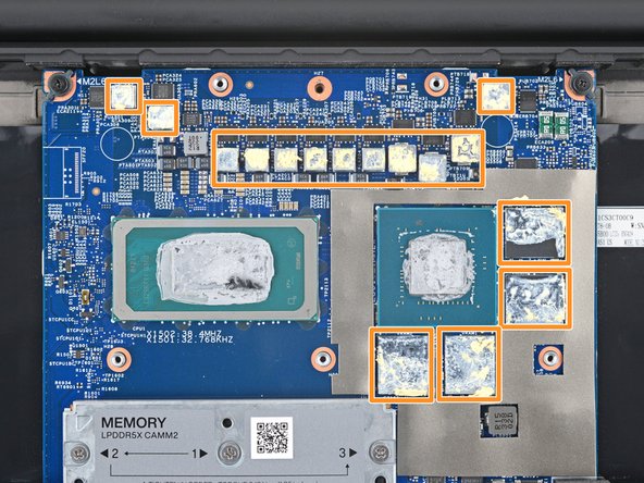
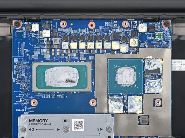
- Remove all the old thermal paste and its residue from the motherboard:
- The CPU and GPU have gray thermal paste on them.
- Depending on the model, your laptop may only have a CPU.
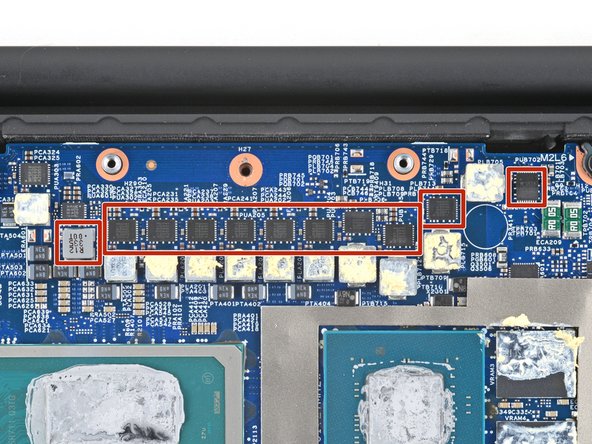
- The components around the CPU and GPU have a yellow, viscous thermal compound.
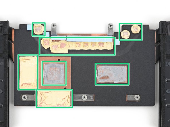
- If you're reusing the heatsink and fan assembly, remove all the old thermal paste and compound from the corresponding spots on its underside.
- Don't remove the small blue pads from the top edge.
- Apply new thermal paste to the CPU and GPU.
- Apply some thermal putty or a viscous thermal compound to the components around the CPU and GPU.
- If you're reusing the assembly, you can skip this step.
- If any of the small blue thermal pads stuck to the top edge of the heatsink, carefully remove and transfer them to their corresponding spots on the motherboard.