Hori D-Pad Controller for Nintendo Switch Teardown
ID: 174150
Description: Made for the gamer on the go, the D-Pad...
Steps:
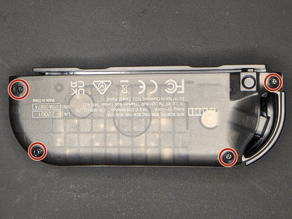
- Remove the four (4) 5.8 mm screws from the back of the controller using a Phillips Head 000 screwdriver
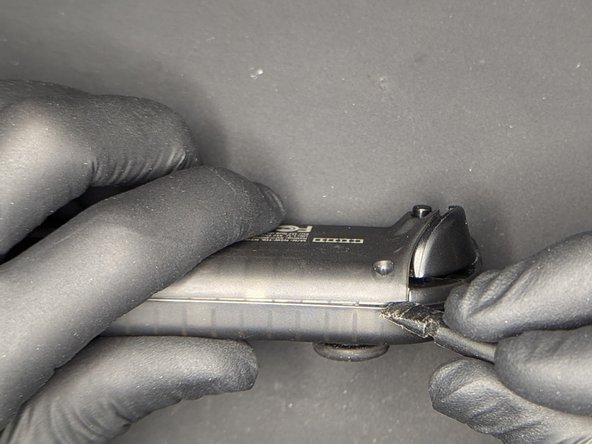
- Use a spudger to open the seam next to the L and ZL buttons
- Follow along the seam until you reach the rail connector
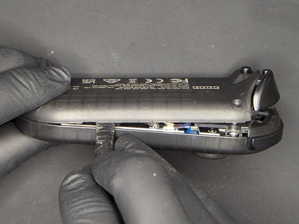
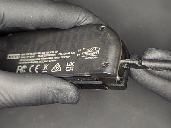
- At the bottom of the controller, apply gentle pressure upwards to separate the top and bottom halves
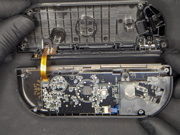
- Gently remove the bottom half of the controller from the top, making sure not to damage the ribbon cable connecting the two
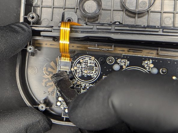
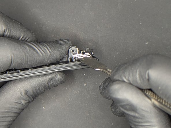
- Gently flip up the door of the connector for the rail ribbon cable
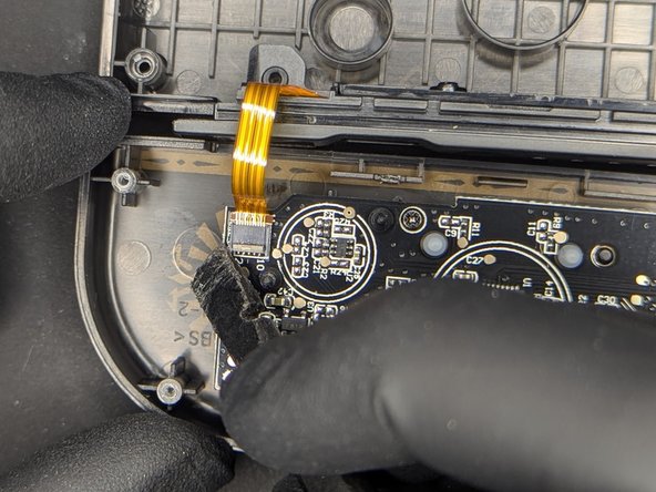
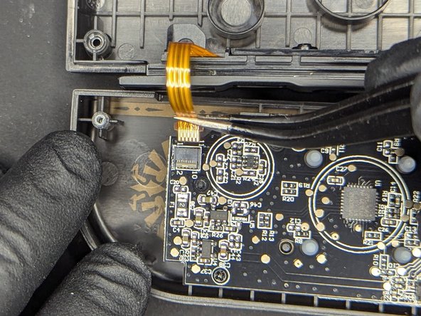
- Remove the ribbon cable from the connector with a tweezers
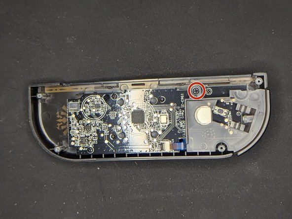
- Remove the 4 mm screw holding the L button in place using a Phillips Head 000 screwdriver
- Remove the plastic bracket holding the L button in place
- Remove the L button
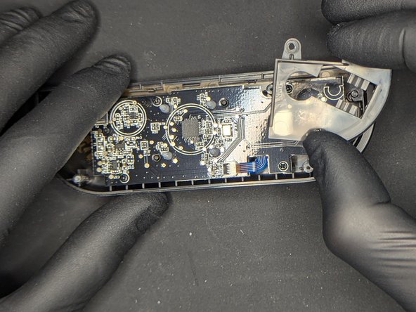
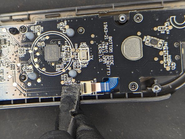
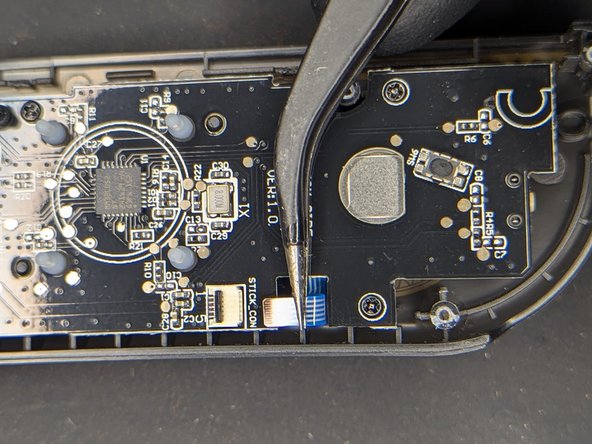
- Gently flip up the door of the connector for the analog stick ribbon cable
- Remove the ribbon cable from the connector with a tweezers
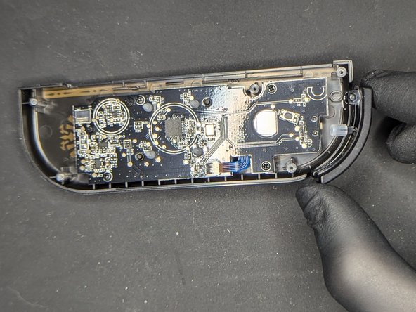
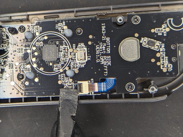
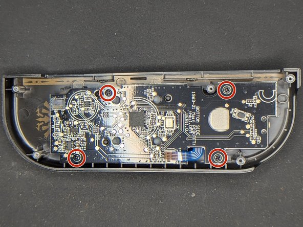
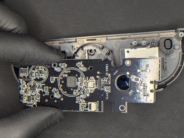
- Remove the four 4 mm screws holding the motherboard in place using a Phillips Head 000 screwdriver
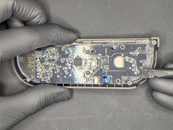
- Gently pry the motherboard away from the front of the controller
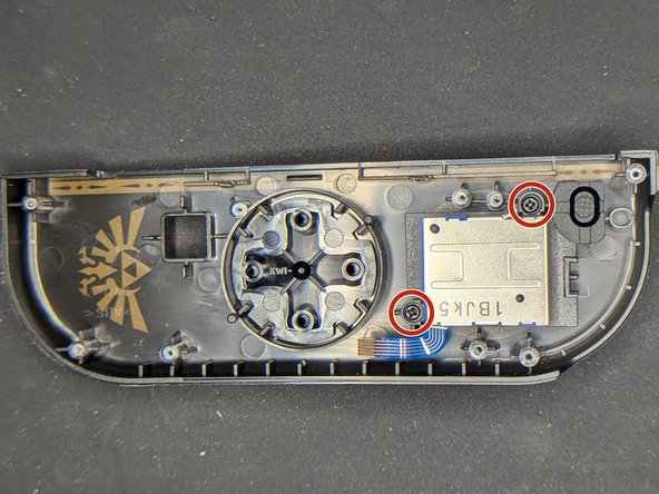
- Remove the two 4 mm screws holding the analog stick in place using a Phillips Head 000 screwdriver
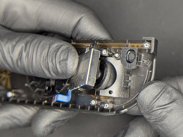
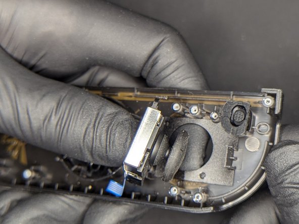
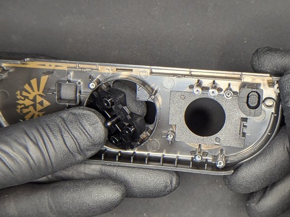
- Applying pressure to the thumbstick from the underside (front) of the controller, gently push the analog through the shell at an angle to remove
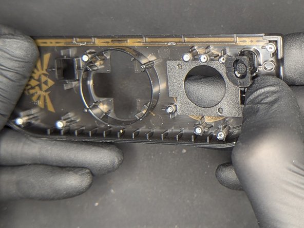
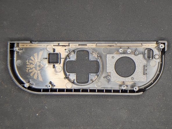
- The D-pad and - buttons can be removed by applying pressure from the underside (front) of the controller
- The dust cover for the analog stick can be lifted and removed from the controller using a pair of tweezers if necessary. This fragile piece is prone to bending and tearing, and will need to be reapplied with double-sided tape.
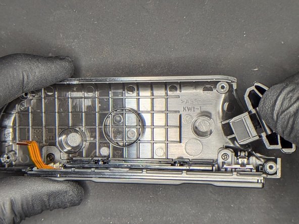
- Lift the ZL button to remove it from the back of the controller
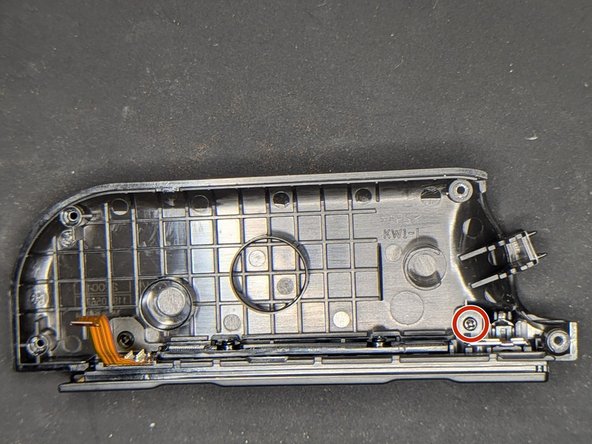
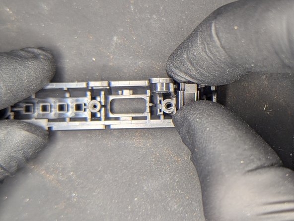
- Remove the 4 mm screw holding the rail in place using a Phillips Head 000 screwdriver
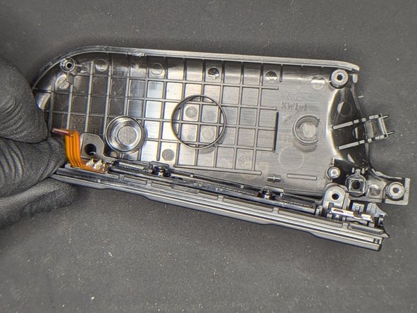
- Lift the rail up and away from the controller shell
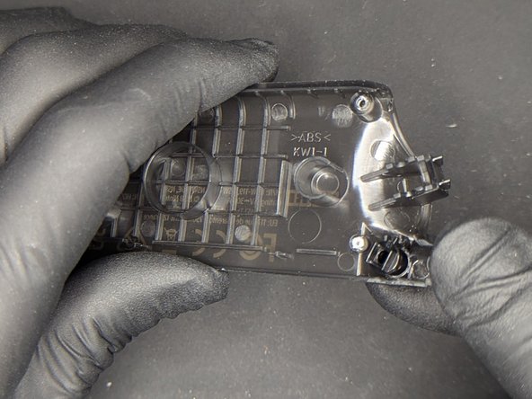
- Apply pressure to the lock release button from the underside (back) of the controller to remove it from the shell
- During reassembly, be sure to properly align the small tab on the back of the button with the intended location on the shell
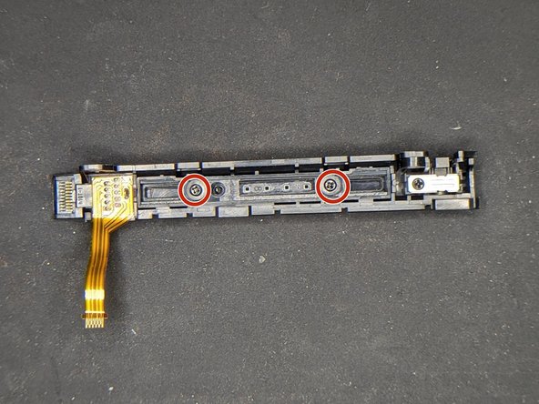
- Remove the two 4 mm screws holding the fake sync indicators in place using a Phillips Head 000 screwdriver
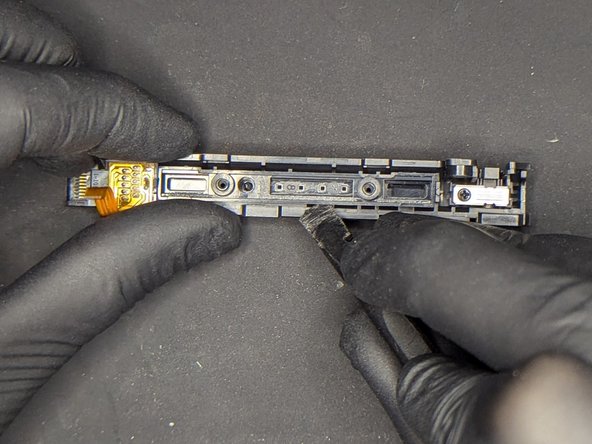
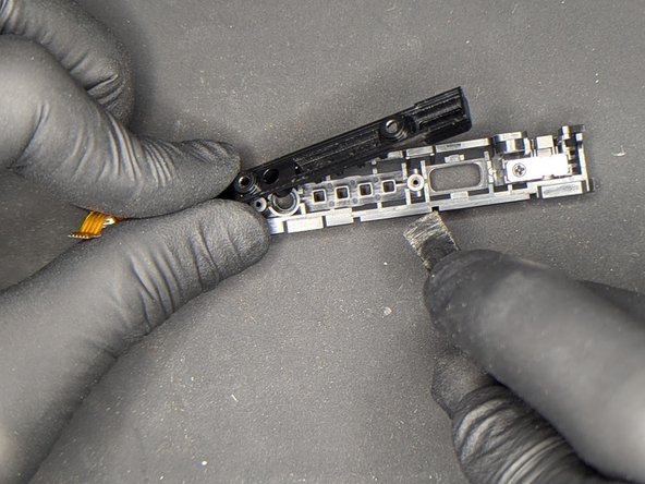
- Use a spudger to lift the plastic piece away from the rail
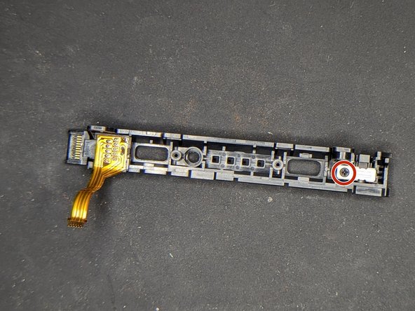
- Remove the 4 mm screw holding the locking mechanism in place using a Phillips Head 000 screwdriver
- Using a spudger, gently lift the metal bracket up and away from the rail
- With extreme caution, lift the locking mechanism up and away from the rail, making sure to retain the small spring that will come out with it.