Lenovo ThinkPad T16 Gen 3 Speakers Replacement
ID: 174369
Description: Follow this guide to replace the speakers in...
Steps:
- For your safety, discharge your battery below 25% before disassembling your laptop. A charged battery may catch fire if damaged. If your battery is swollen, take appropriate precautions.
- Completely shut down your laptop (don't just put it in sleep mode) and disconnect all cables.
- Flip the laptop upside-down, and rotate it so the screen hinge faces towards you.
- Use a Phillips screwdriver to fully loosen the seven captive screws securing the base cover.
- Insert your fingernail or an opening pick into the gap between the base cover and keyboard deck, next to one of the screen hinges.
- Pry up the base cover until the clips unfasten.
- Grasp the base cover along the screen hinge edge and lift slowly to unfasten the remaining clips.
- Lift and remove the base cover.
- During reassembly, lay the base cover into the frame, inserting it into the tabs along the battery edge. Press down firmly around the perimeter to reengage all the clips.
- Because of the battery connector's design, the only way to disconnect the battery is by physically removing it.
- Use a Phillips screwdriver to fully loosen the two captive screws securing the battery connector.
- Lift the edge of the battery with the connector to disconnect it.
- You may feel a little resistance from the battery connector as it disconnects—that's normal.
- Remove the battery
- During reassembly:
- Slide the plastic tabs on the long edge of the battery into their recesses in the frame.
- Lower the battery into place so the connector goes over its socket.
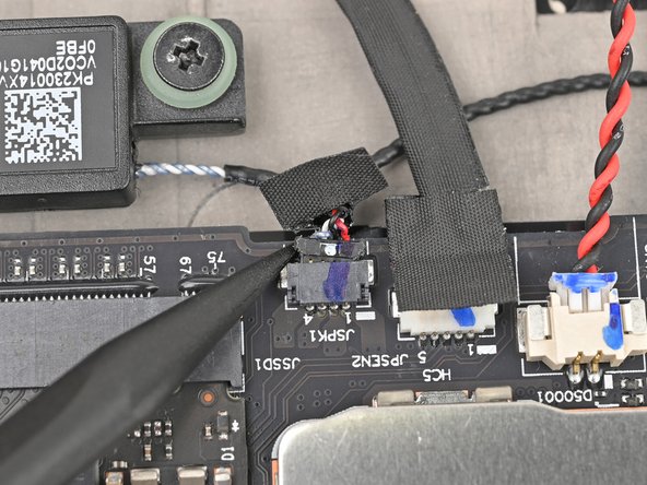
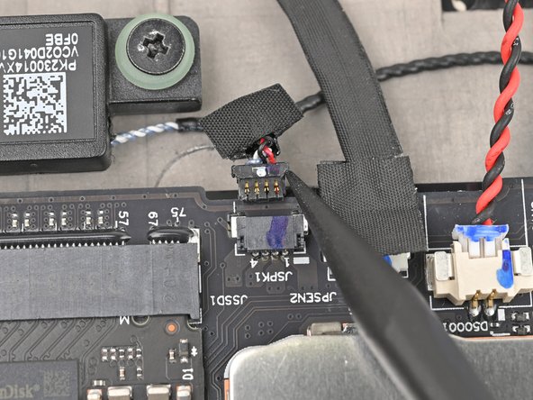
- Use your fingernails to grip the right speaker connector by the lip near the back and gently pull the connector out of its socket (labeled "JSPK1").
- Alternatively, you can use the point of a spudger to push on alternating sides of the connector to walk it out of the socket.
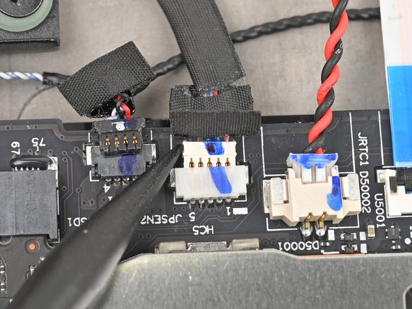
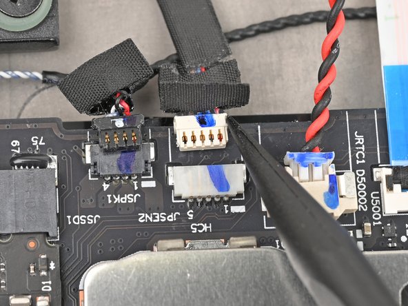
- Use your fingernails to grip the WWAN antenna connector by the lip near the back and gently pull the connector out of its socket (labeled "JPSEN2").
- Alternatively, you can use the point of a spudger to push on alternating sides of the connector to walk it out of the socket.
- Use your fingernails to grip the CMOS battery connector by the lip near the back and gently pull the connector out of its socket (labeled "JRTC1").
- Alternatively, you can use the point of a spudger to push on alternating sides of the connector to walk it out of the socket.
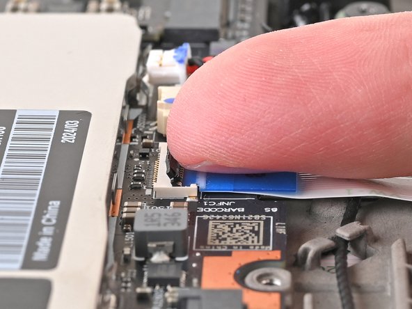
- Use a clean fingernail or the flat end of a spudger to flip up the locking flap on the NFC interconnect cable connector, labeled "JNFC1."
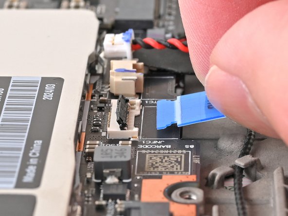
- Use tweezers or your fingers to grip the cable's plastic pull tab and gently pull the cable out of its socket.
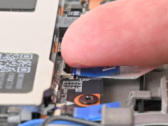
- Use a clean fingernail or the flat end of a spudger to flip up the locking flap on the trackpad interconnect cable connector, labeled "JCP1."
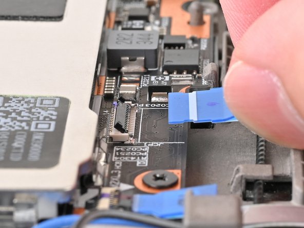
- Use tweezers or your fingers to grip the cable's plastic pull tab and gently pull the cable out of its socket.
- Use a clean fingernail or the flat end of a spudger to flip up the locking flap on the smart card reader interconnect cable connector, labeled "JSC1."
- Use tweezers or your fingers to gently pull the cable by its pull tab out of its socket.
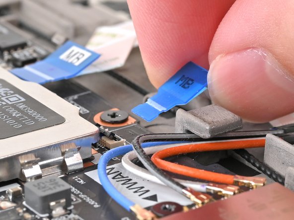
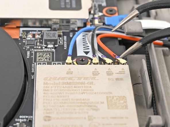
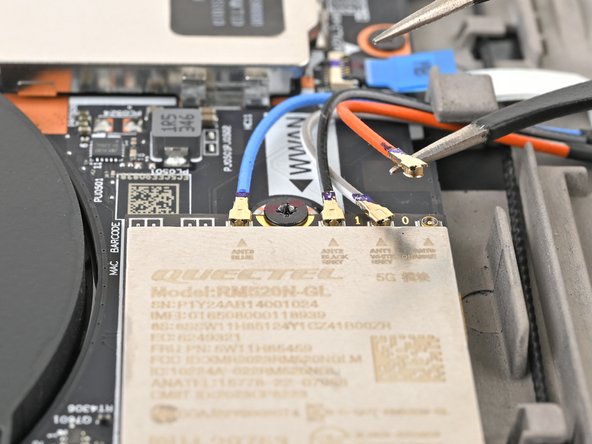
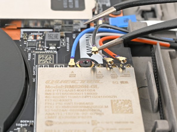
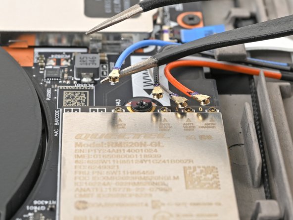
- Insert one arm of your angled tweezers under the metal neck of one of the antenna coaxial connectors on the WWAN card and lift straight up to disconnect it.
- Repeat the process to disconnect the remaining antenna cables from the WWAN card.
- During reassembly, use tweezers to hold each connector in place over its socket and gently press down with your finger or a spudger—the connector should "snap" into place. If you're having trouble, reposition the head instead of using more force.
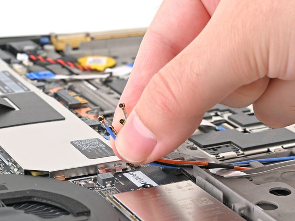
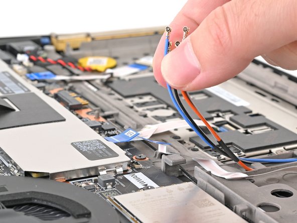
- Hold all the antenna cables together and weave them out of the clips holding it to the chassis.
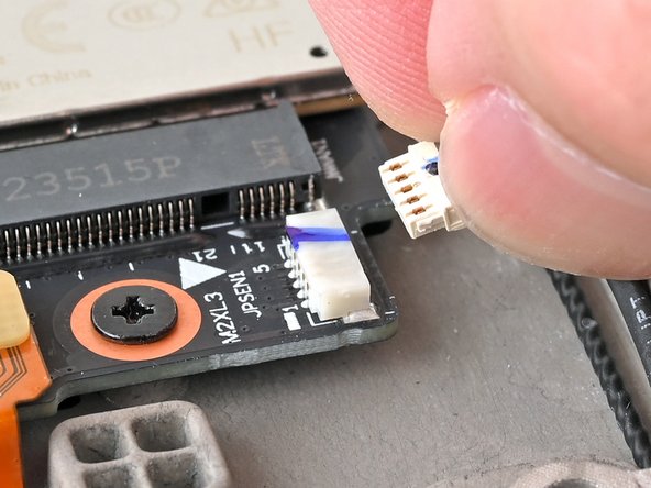
- Use your fingernails to grab on the lip located at the back of the WWAN antenna connector labeled "JPSEN1."
- Alternatively, you can use the point of a spudger to push on alternating sides of the connector to walk it out of the socket.
- Unplug the connector from the motherboard.
- Many of these connectors have a small marking that shows which side of the connector should be facing up. To reconnect, align the connector and use a spudger or clean fingernail to push it fully into the socket.
- Use your fingers to guide the JPSEN1 cable out of its clips on the chassis.
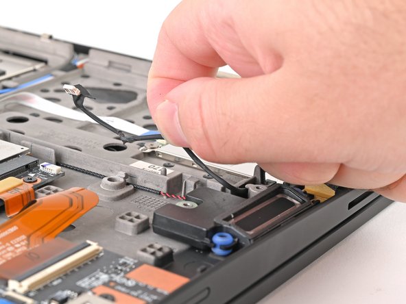
- Use a Phillips screwdriver to remove the two 3 mm‑long screws securing the speakers (one in each).
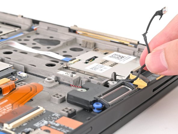
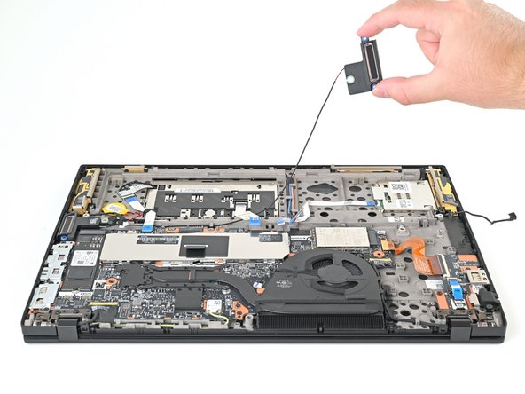
- Lift one of the speakers off its post and guide the speaker cable out of its clips in the center of the laptop.
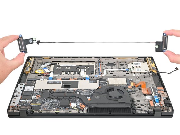
- Once the cable is unclipped, remove the other speaker.
- During reassembly, make sure your replacement speakers have rubber grommets installed on the top, middle, and bottom edges. If they don't, transfer them from your old speakers.