HP 15-fc0000 Series Trackpad Replacement
ID: 174420
Description: Use this guide to replace the trackpad in your...
Steps:
- Shut down the laptop.
- Unplug the charger and any other cables from the laptop.
- Close the laptop and flip it over so the rubber feet are facing up. Place the laptop on a soft surface to avoid damaging the top cover.
- Use a Phillips screwdriver to remove the four screws securing the bottom cover.
- Two 6.8 mm‑long screws near the rear of the laptop.
- Two 4.8 mm‑long screws near the front of the laptop.
- The clips attached to the bottom cover are fragile. Use caution when releasing them.
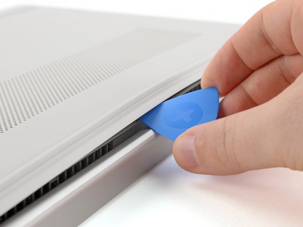
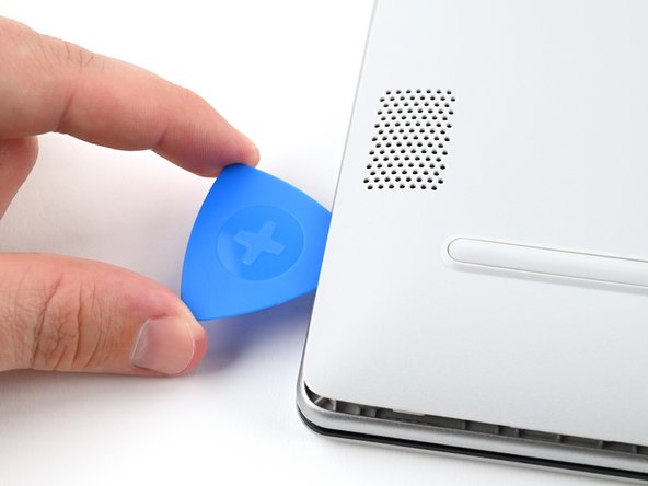
- Insert an opening pick under the bottom cover at the rear of the laptop.
- Twist the pick until one or more clips release.
- Repeat this procedure along the rear edge until you release all the clips.
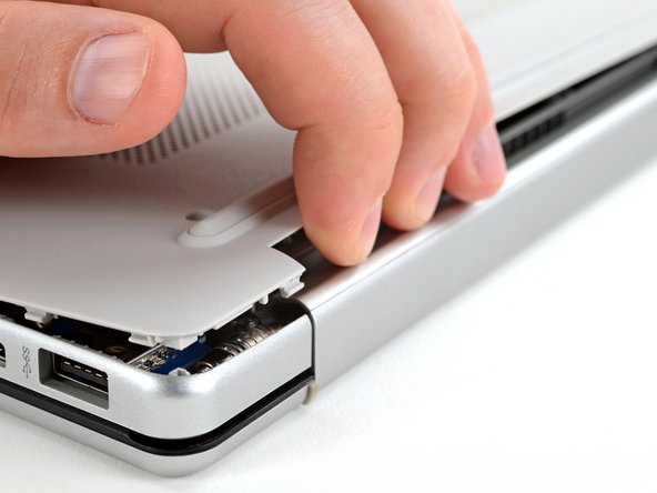
- The bottom cover is fragile. Use caution when bending it.
- Place your fingers under the part of the bottom cover you've raised, near a corner.
- Use your fingers to gently pry up the corner of the bottom cover.
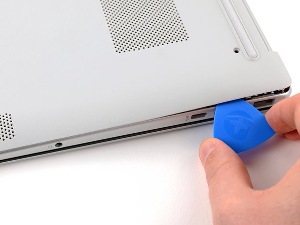
- Insert an opening pick under the edge of the bottom cover next to the corner you've raised.
- Pry up the back cover clips along the edge.
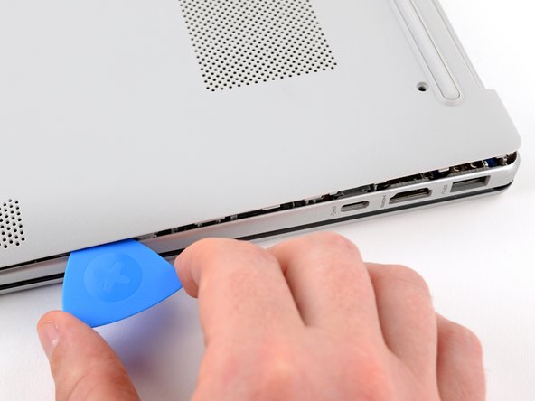
- Use an opening pick to repeat the procedure from the previous step to pry up the remaining sides of the bottom cover.
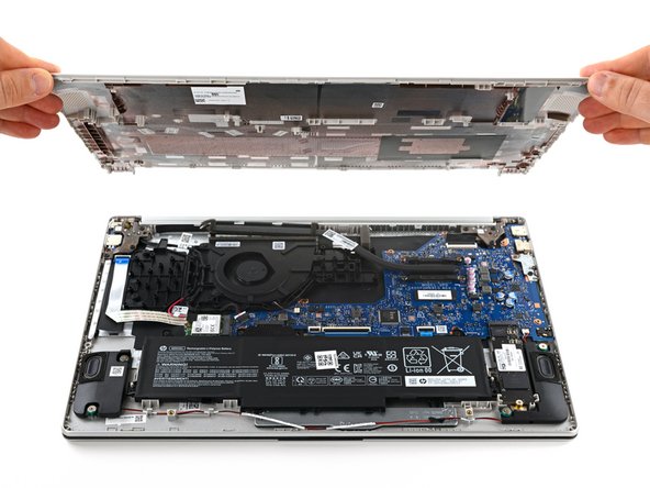
- Remove the bottom cover.
- Some clips may re-engage when you're releasing other sides. If the bottom cover doesn't lift off easily, use the opening pick to release any remaining clips.
- During reassembly, lay the bottom cover on the laptop so the sides of the cover align with the sides of the laptop. Then, gently press on the sides until you hear the clips click. If the clips don't engage easily, adjust the cover and try again.
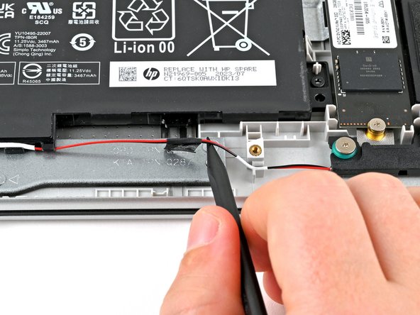
- Do not put too much stress on the wire, as that can harm your laptop's audio quality.
- Use a spudger or your fingers to lift the tape that adheres the speaker wires to the metal trackpad bracket.
- Try not to fold the tape so it can be reused during reassembly.
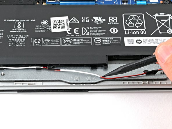
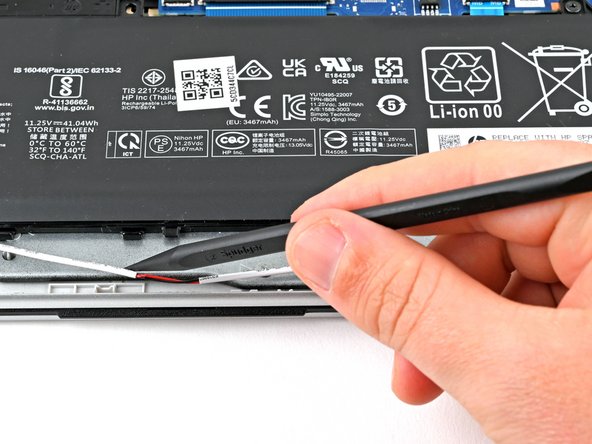
- Use a spudger or your fingers to remove the speaker wires from the routing clips along the edge of the battery.
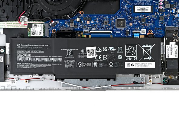
- Use a Phillips screwdriver to remove the five 4.3 mm‑long screws securing the battery.
- During reassembly, press firmly on the battery connector to ensure a strong connection.
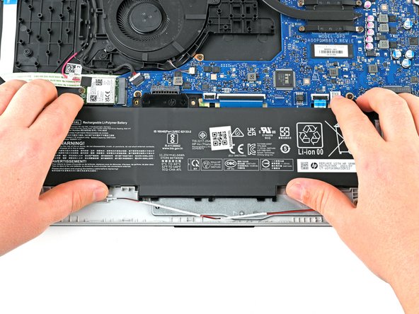
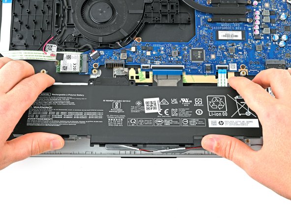
- Do not grab the battery at the ends because this battery is flexible. Instead, grab the battery one inch from each end to better support the middle.
- Use two hands to grip the battery about one inch from each end.
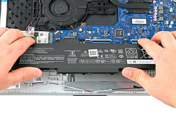
- Lift the front of the battery (the side closest to you) until the battery is free of its alignment pegs.
- Pull the battery towards you to release it from its connector.
- Don't continue to use a damaged battery, as doing so is a potential safety hazard. If in doubt, replace it with a new battery.
- During reassembly, insert the battery onto its connector at a slight downward angle before pressing it flat to the frame.
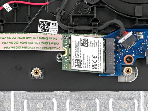
- Use tweezers to remove the plastic cover on the wireless LAN card antenna cable.
- Set the plastic cover aside with the sticky side up.
- Keep the adhesive on the back of the plastic cover clean, as you will reuse this during reassembly.
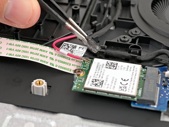
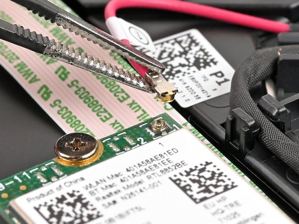
- Place one arm of a pair of tweezers under the metal head of the antenna cable. Lightly grip the head.
- The pictured laptop only has one antenna cable, but yours may have two.
- Lift straight up to disconnect the antenna.
- It's important to lift the connector straight up. If lifted at an angle, you risk breaking the socket off of the board underneath.
- Use tweezers to hold the connector in place over its socket and gently press down with your finger or a spudger—the connector should "snap" into place. If you're having trouble, reposition the head and try again.
- Don't try to force the connector into place or you may permanently damage it.
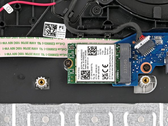
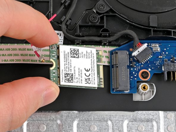
- Use a Phillips screwdriver to remove the 3.1 mm‑long screw securing the wireless LAN card.
- The wireless LAN card will spring up at an angle after the screw is removed.
- Grip the wireless LAN card by its edges and pull it away from its socket to remove it.
- During reassembly, insert the card into its socket at an angle before pressing it flat to the laptop.
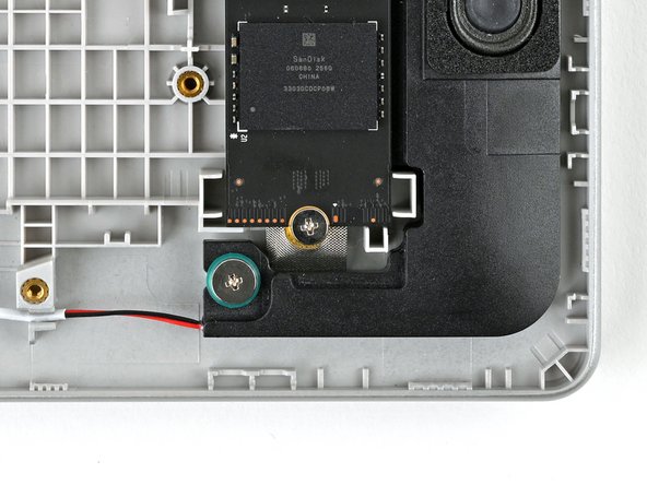
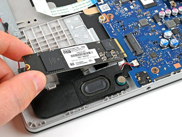
- Use a Phillips screwdriver to remove the 3.8 mm‑long screw securing the SSD.
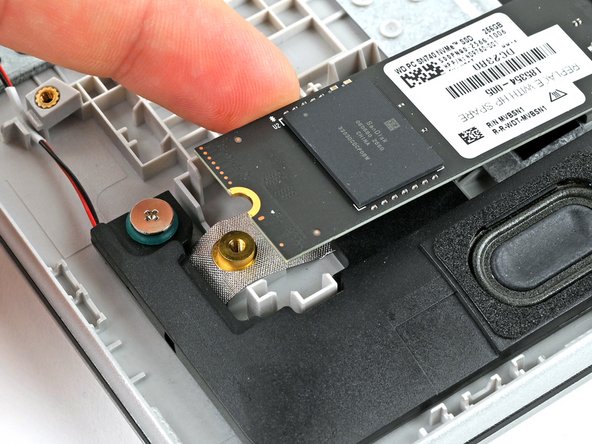
- Lift the edge of the SSD near the screw indent to a shallow angle.
- Grip the SSD by its edges and pull it away from its socket to remove it.
- During reassembly, insert the SSD into its socket at a shallow angle before lowering it flat to the laptop.
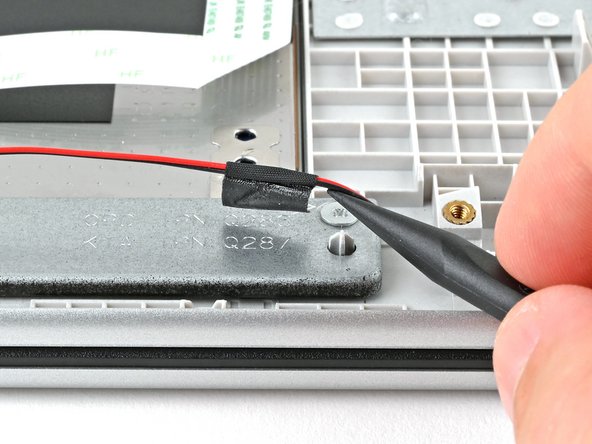
- This tape may still be lifted from an earlier step. If so, skip this step.
- Do not put too much stress on the wire, as that can harm your laptop's audio quality.
- Use a spudger or your fingers to lift the tape that adheres the speaker wires to the metal touch pad bracket.
- Try not to fold the tape because it can be reused during reassembly.
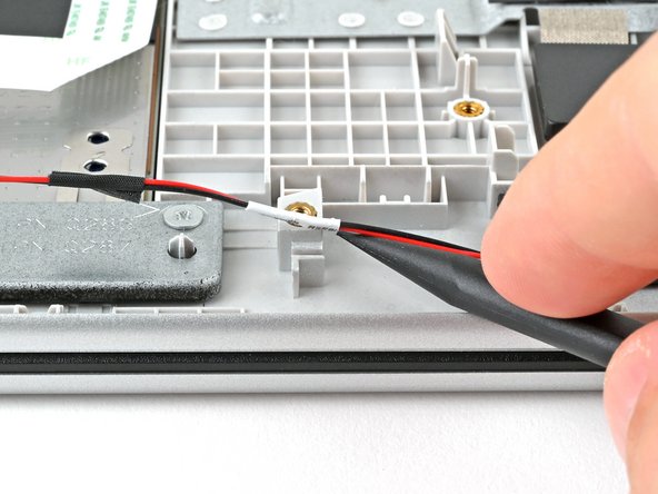
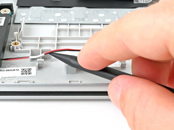
- Use a spudger to lift the speaker wire out of the routing clip near the left speaker.
- The left speaker is on your right, since the laptop is upside down.
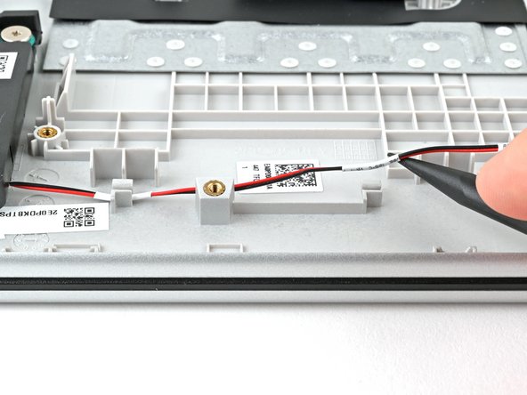
- Repeat the procedure from the previous step to lift the speaker wire out of the two routing clips near the right speaker.
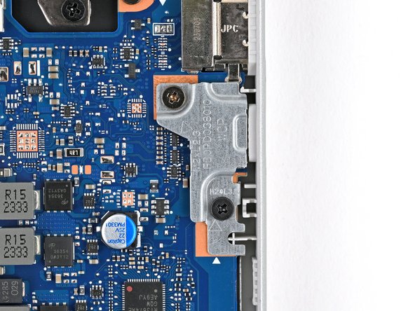
- Use a Phillips screwdriver to remove the two screws securing the USB-C port bracket.
- One 3.1 mm‑long screw
- One 4.3 mm‑long screw
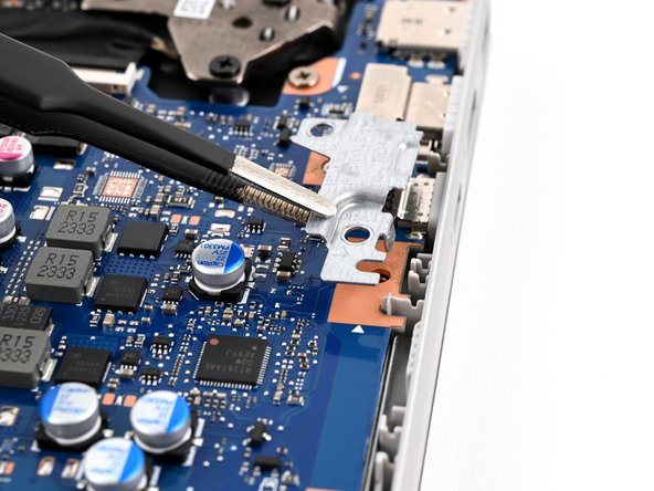
- Use tweezers or your fingers to lift the bracket off the USB-C port and remove it.
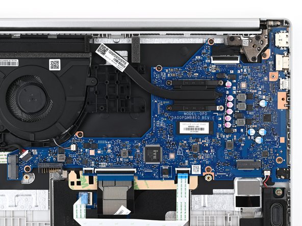
- The next ten steps instruct how to disconnect each connector on the motherboard. Refer to the Recognizing and Disconnecting Cable Connectors guide for more help.
- DC-in
- Fan
- Display
- Speakers
- Trackpad
- Keyboard
- Make sure all cables and wires connected to the top of the motherboard are disconnected before lifting the motherboard. Depending on the configuration of your laptop, you may have a different number of connectors to disconnect.
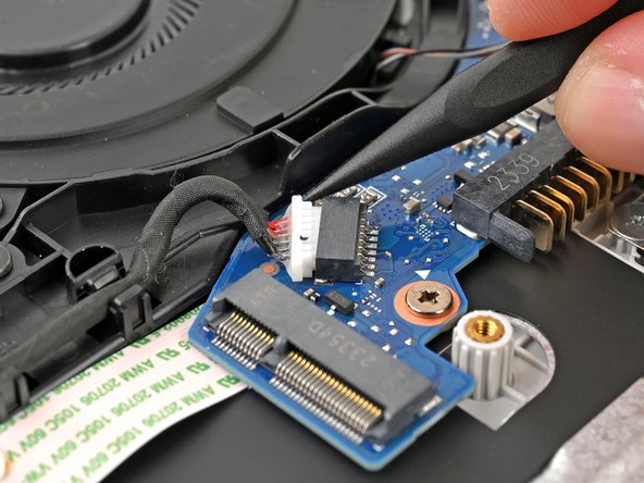
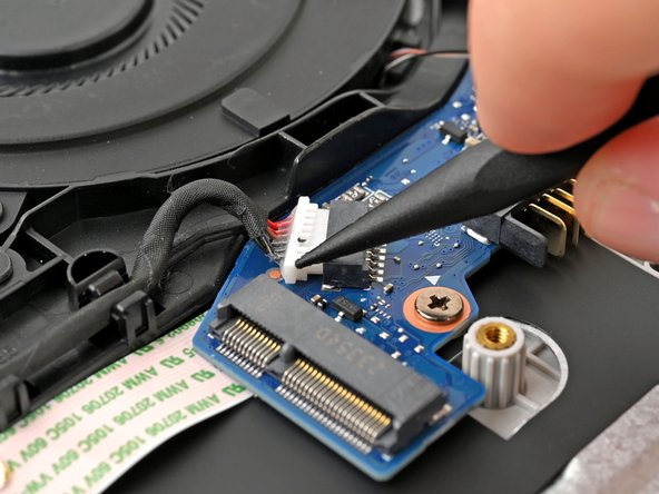
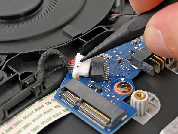
- Use a spudger to "walk" the DC‑in cable out of its socket on the system board by pushing on alternating sides of the white connector.
- Once the cable is loose, use a spudger to push the DC‑in cable out of its socket on the system board.
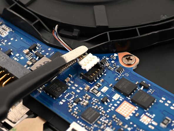
- Insert one arm of blunt nose tweezers under the fan cable, as close to the connector as possible.
- Grip the wires evenly and lift the cable up to disconnect the fan.
- To reconnect the fan to the motherboard, use a pair of tweezers to grip all of the wires and align the connector with the socket. Then, use the flat end of a spudger or your finger to evenly press the connector into the socket.
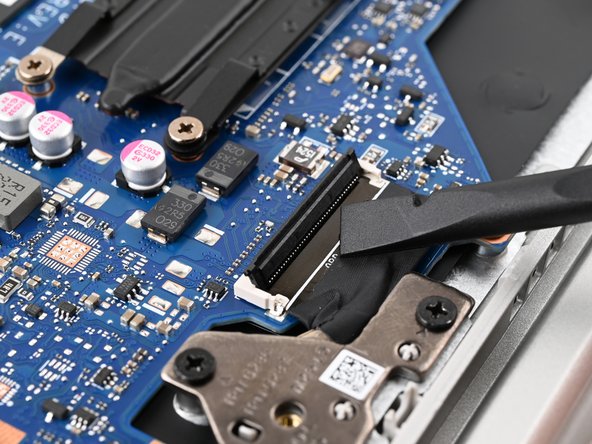
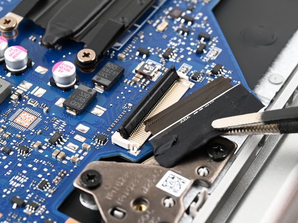
- Use the flat end of a spudger to lift up the black locking tab on the USB Board ZIF connector.
- Use tweezers or your fingers to grip the black taped portion of the display cable.
- Pull the ribbon cable away from its connector to disconnect it.
- When reconnecting this cable, make sure the locking tab is fully open (up). The cable should slide in with minimal force. If you feel resistance, check that the locking tab is fully open and the cable is aligned, then try again.
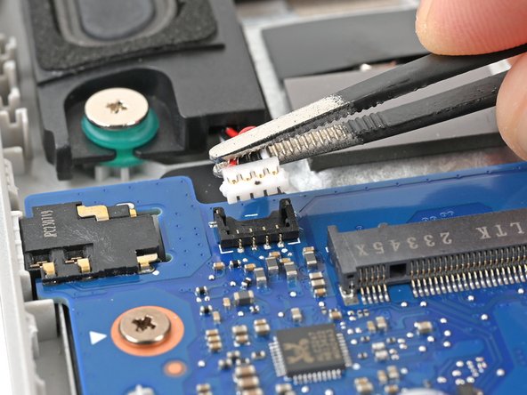
- Insert one arm of blunt nose tweezers under the speaker cable, as close to the connector as possible.
- Grip the wires evenly and lift the cable up to disconnect the fan.
- To reconnect the speakers to the motherboard, use a pair of tweezers to grip all of the wires and align the connector with the socket. Then, use the flat end of a spudger to evenly press the connector into the socket.
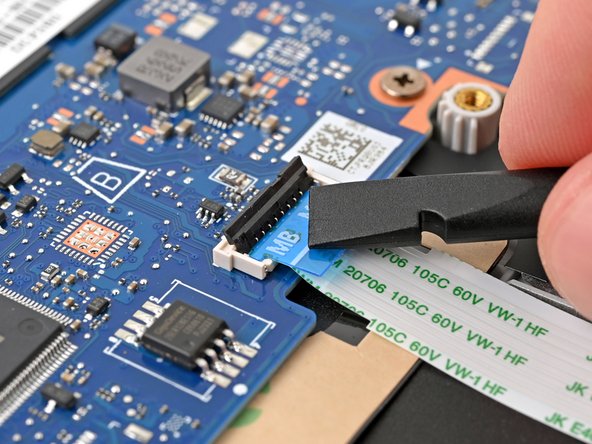
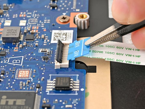
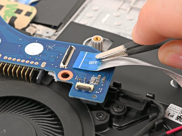
- Use the flat end of a spudger to lift up the black locking tab on the trackpad ZIF connector.
- Use tweezers or your fingers to grip the blue pull tab marked "MB."
- Pull the ribbon cable away from its connector to disconnect it.
- When reconnecting this cable, make sure the locking tab is fully open (up). The cable should slide in with minimal force. If you feel resistance, check that the locking tab is fully open and the cable is aligned, then try again.
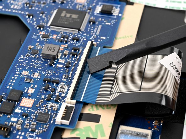
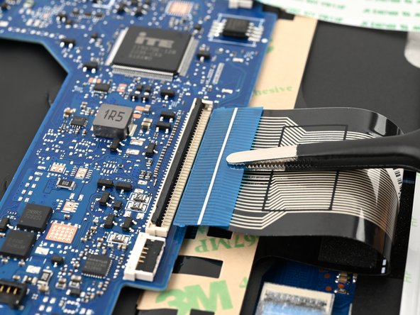
- Use the flat end of a spudger to lift up the black locking tab on the keyboard ZIF connector.
- Use tweezers or your fingers to grip the blue pull tab on top of the display ribbon cable.
- Pull the ribbon cable away from its connector to disconnect it.
- When reconnecting this cable, make sure the locking tab is fully open (up). The cable should slide in with minimal force. If you feel resistance, check that the locking tab is fully open and the cable is aligned, then try again.
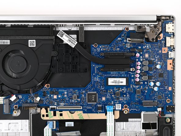
- Use a Phillips screwdriver to remove the seven 3.1 mm‑long screws securing the motherboard.
- Make sure all cables are disconnected from the top of the motherboard. Your laptop may have more cables than those listed here.
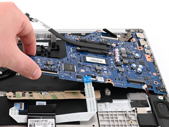
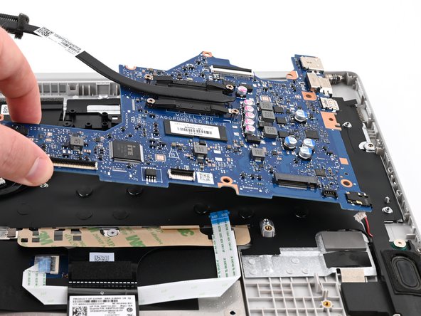
- Remove the motherboard from its slot in the frame by lifting the left edge.
- Pull the motherboard to the left and guide the external ports out of their slots.
- The USB-A board cable is still attached to the back of the board, so don't try to remove the board entirely yet.
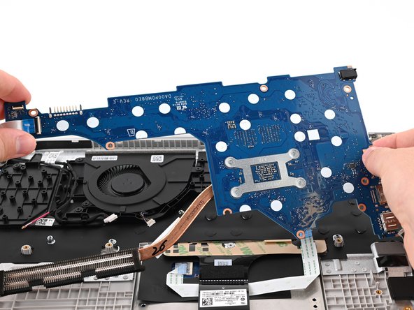
- Flip the motherboard over and gently lay it on the laptop so you can access the remaining cable connector.
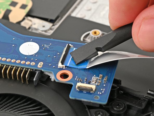
- On the back of the motherboard (now facing up), use the flat end of a spudger to pry up the black locking tab on the USB board ZIF connector on the motherboard.
- Use tweezers or your fingers to grip the blue pull tab marked "MB."
- Pull the ribbon cable away from its connector to disconnect it.
- When reconnecting this cable, make sure the locking tab is fully open (up). The cable should slide in with minimal force. If you feel resistance, check that the locking tab is fully open and the cable is aligned, then try again.
- Make sure all cables are disconnected from both sides of the motherboard. Your laptop may have more cables than those listed here.
- Remove the motherboard.
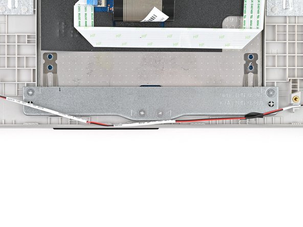
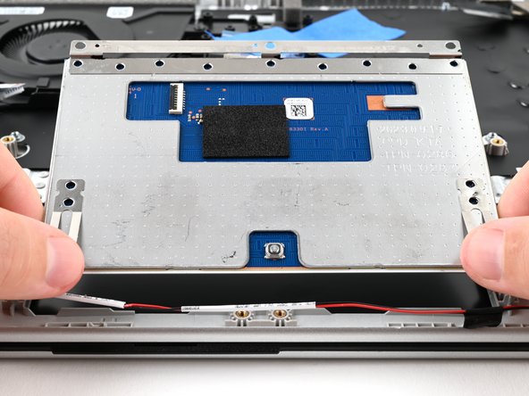
- Use a Phillips screwdriver to remove the four 2.0 mm‑long screws securing the trackpad bracket.
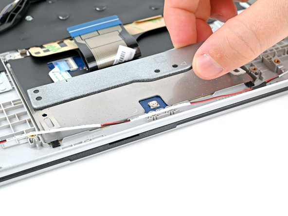
- Use your fingers to lift the trackpad bracket and remove it.
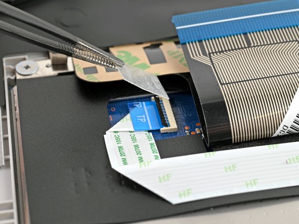
- Use tweezers to remove the plastic cover over the trackpad ribbon cable connector.
- Place this cover somewhere safe with the adhesive side up, so it can be reapplied during reassembly.
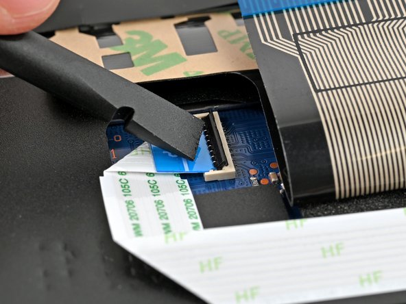
- Use the flat end of a spudger to pry up the black locking tab on the trackpad ZIF connector located on the back of the trackpad.
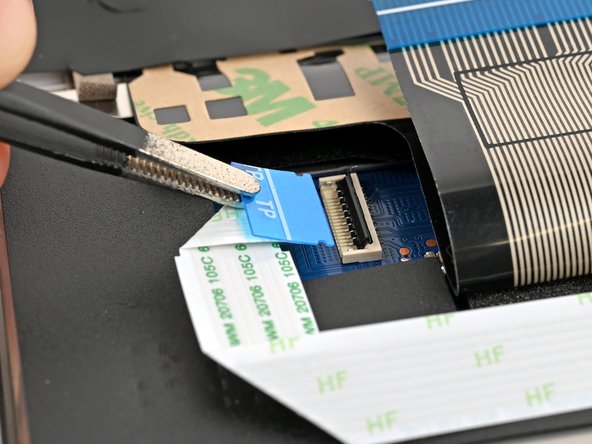
- Use tweezers or your fingers to grip the blue pull tab marked "TP."
- Pull the ribbon cable away from its connector to disconnect it.
- When reconnecting this cable, make sure the locking tab is fully open (up). The cable should slide in with minimal force. If you feel resistance, check that the locking tab is fully open and the cable is aligned, then try again.
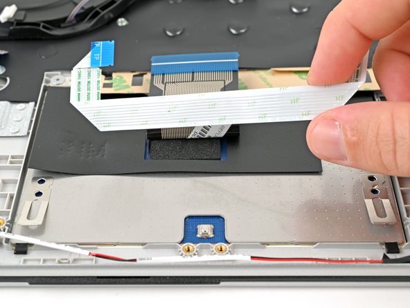
- Use your fingers or tweezers to remove the entire trackpad ribbon cable and set it aside.
- This cable may be lightly adhered to the black mylar under it. Avoid bending the ribbon cable by using the flat end of a spudger or tweezers to pry up the ribbon cable anywhere it's adhered.
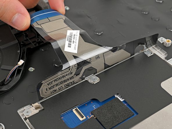
- Use your fingers to grip either side of the loose end of the keyboard ribbon cable.
- Pull the ribbon cable back towards the rear of the laptop to get the entire ribbon cable off of the trackpad.
- It helps to tape this out of the way using painter's tape or masking tape.
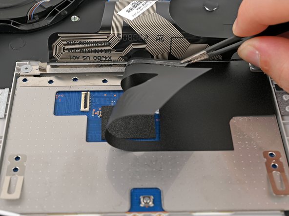
- Use a pair of tweezers or your fingers to peel back the mylar that covers the trackpad.
- This mylar is adhered along the top of the trackpad (towards the rear of the laptop). Grip the mylar along this top edge to avoid stretching or breaking the mylar.
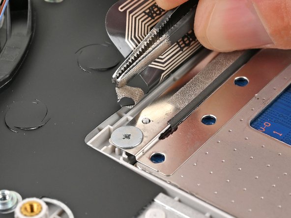
- Use tweezers to peel the grounding tape off the trackpad, still leaving it attached to the laptop frame.
- The grounding tape on this device is on the top-left corner of the trackpad. Yours may be somewhere else along the top of the trackpad.
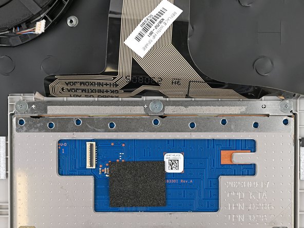
- Use a Phillips PH000 screwdriver to remove the three 2.4 mm‑long screws securing the trackpad.
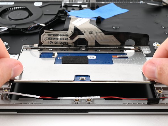
- Use your fingers to lift the front edge of the trackpad and remove it.