Acer Aspire 3 A315-24P-R7VH Motherboard Replacement
ID: 174459
Description: Use this guide to replace the motherboard for...
Steps:
- Shut down your laptop and unplug any cables.
- Close the laptop and flip it over on a flat, clean surface.
- Use a Phillips screwdriver to remove the eleven 6.6 mm‑long screws from the back cover.
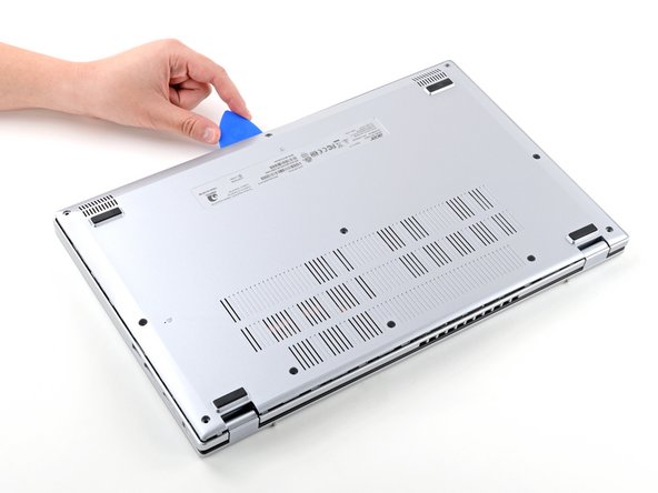
- Insert the long edge of an opening pick straight down between the chassis and the back cover at the rear of the laptop
- Pry up to release a few back cover clips and position the opening pick flat under the back cover.
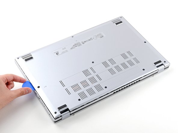
- Slide the pick along the rear edge of the laptop to release the clips.
- Pry around the entire perimeter until the back cover releases.
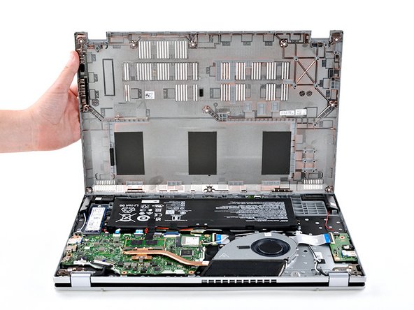
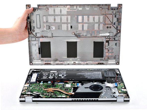
- Lift the back cover off the chassis and remove it.
- If the back cover is stuck, repeat the previous step to release any remaining clips.
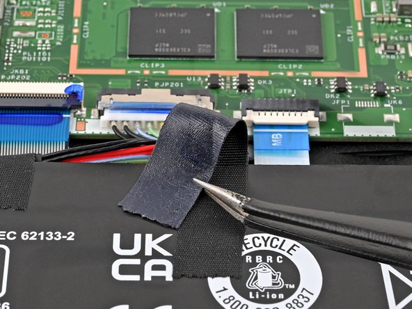
- Use tweezers or your fingers to peel away the tape covering the battery connector.
- Use the tip of a spudger to push down on either side of the battery cable connector until it comes out of its socket.
- Use a Phillips screwdriver to remove the two 4.7 mm‑long screws securing the battery.
- Lift the battery out of the chassis and remove it.
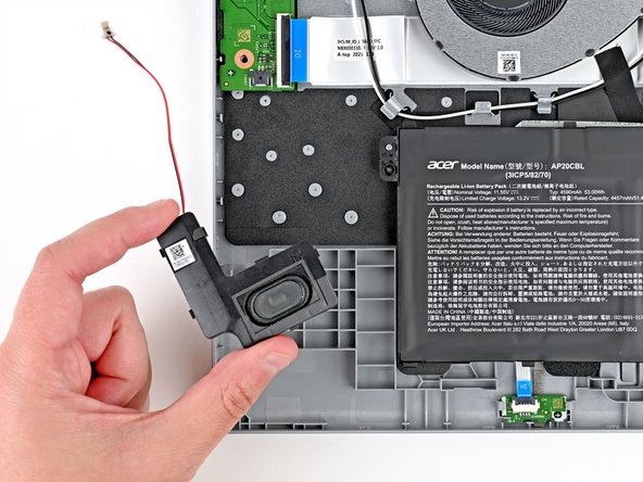
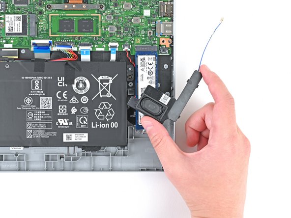
- Use the tip of a spudger to push down on either side of the right speaker cable connector until it comes out of its socket.
- The right speaker is on the left-hand side since your laptop is upside down.
- Repeat the same procedure for the left speaker.
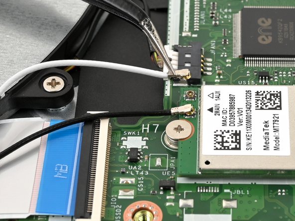
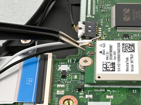
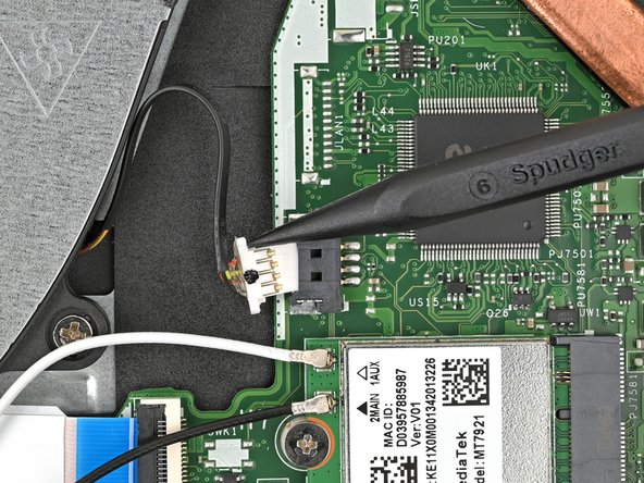
- Slide one arm of your angled tweezers under the metal neck of the white cable on the WLAN card.
- Lift the metal neck to disconnect the cable.
- Repeat the same process for the black cable.
- When reassembling, use tweezers to hold the connector in place over its socket and gently press down with your finger or a spudger—the connector should "snap" into place. It may take multiple tries repositioning the head until it reconnects.
- Don't try to force the connector into place or you may permanently damage it.
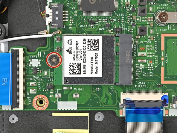
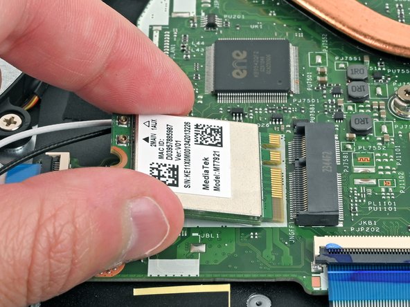
- Use a Phillips screwdriver to remove the 2.2 mm‑long screw from the WLAN card.
- The WLAN card will pop up at a slight angle with the screw removed.
- Pull the WLAN card out of its socket and remove it.
- During reassembly, insert the WLAN card at a slight downward angle into its socket.
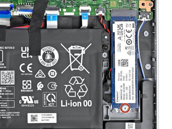
- Use a Phillips screwdriver to remove the one 4.9 mm‑long screw securing the SSD.
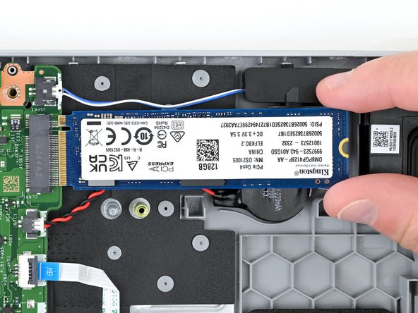
- Grip the SSD by its edges and pull it straight out of its socket to remove it.
- Don't pull up at a sharp angle, as this could damage the SSD and its socket.
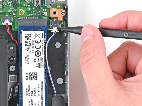
- Use the tip of a spudger to push down on either side of the fan cable connector until it comes out of its socket.
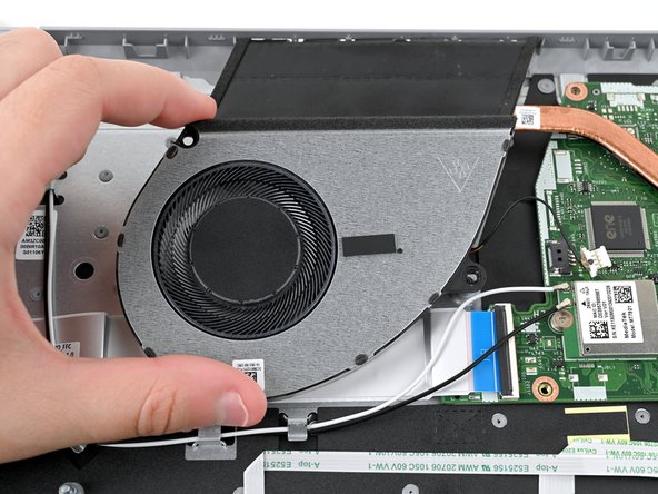
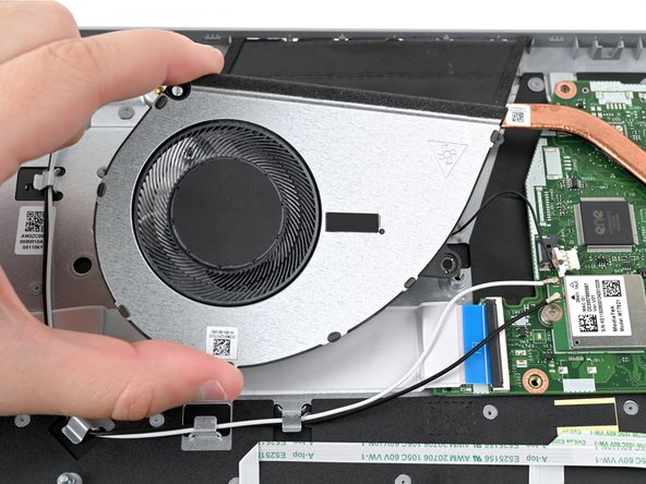
- Use a Phillips screwdriver to remove the two 5.6 mm‑long screws that are securing the fan.
- Lift the fan out of the chassis and remove it.
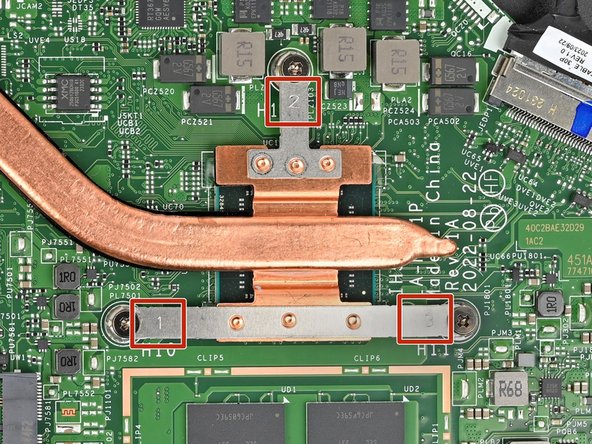
- Starting with the screw labeled 1 and going in order, use a Phillips screwdriver to remove the three 4.7 mm‑long screws that secure the heat sink.
- During reassembly, tighten the screws in the same order as you removed them.
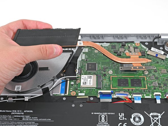
- Lift the heat sink to separate the thermal paste bonding it to the motherboard.
- Remove the heat sink.
- Before installing a new heat sink, follow this guide to clean the CPU and heat sink and reapply thermal paste.
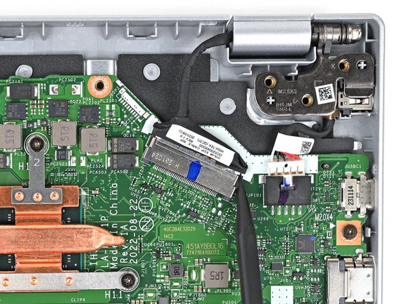
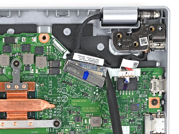
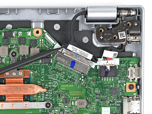
- Use the tip of a spudger to push down on either side of the display cable connector until it comes out of its socket.
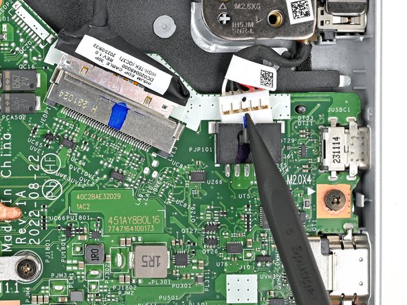
- Use the tip of a spudger to push the indent on DC-IN cable connector until it comes out of its socket.
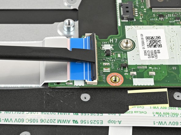
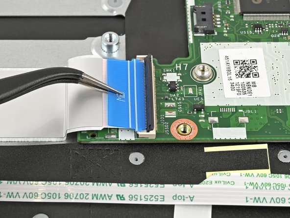
- Use the flat end of a spudger or a fingernail to lift the locking tab on the USB board ZIF connector.
- Use a pair of tweezers or your fingers to grasp the blue pull tab and gently pull the cable out of its socket.
- This cable is very fragile, try not to crease or kink the cable.
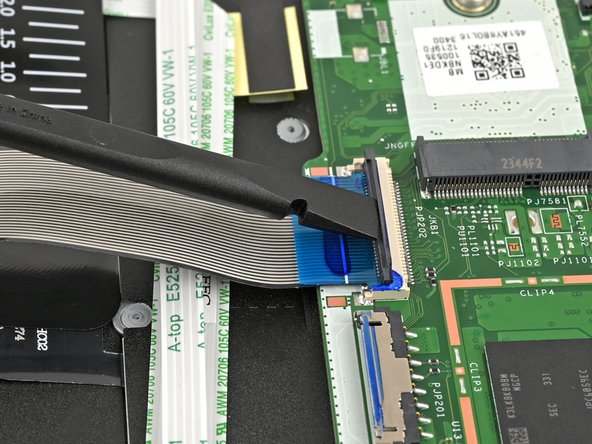
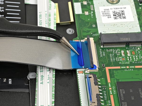
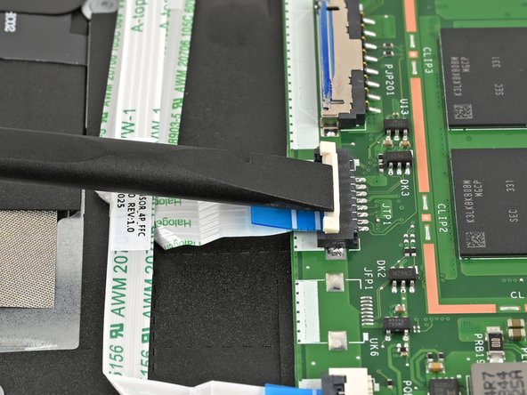
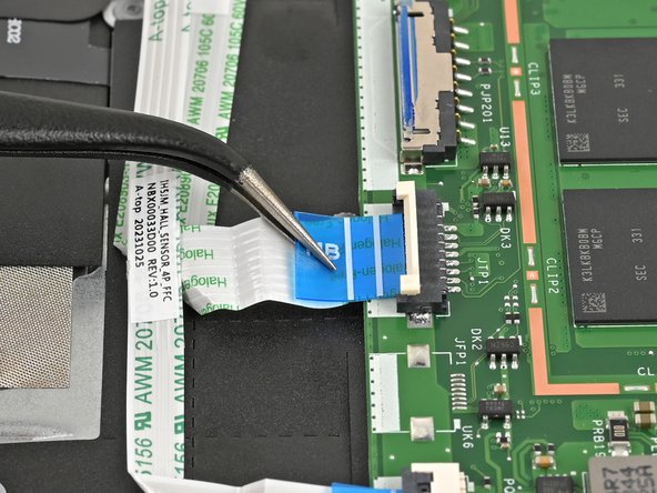
- Use the flat end of a spudger or a fingernail to lift the locking tab on the keyboard ZIF connector.
- Use a pair of tweezers or your fingers to grasp the blue pull tab and gently pull the cable out of its socket.
- This cable is very fragile, so be careful not to crease or fold the cable.
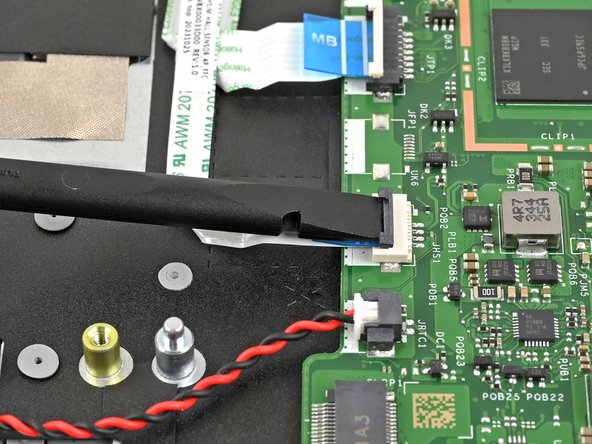
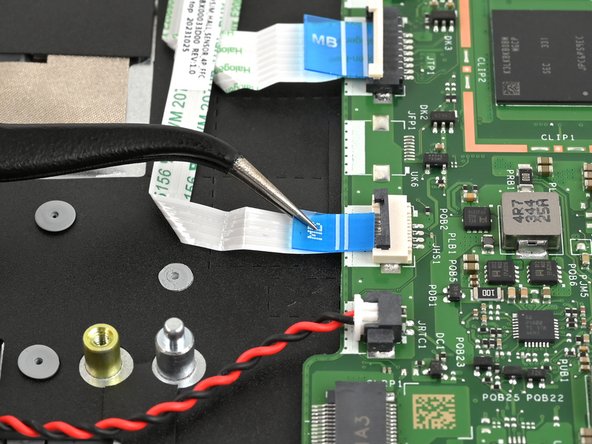
- Use the flat end of a spudger or a fingernail to lift the locking tab on the touchpad ZIF connector.
- Use a pair of tweezers or your fingers to grasp the blue pull tab and gently pull the cable out of its socket.
- This cable is very fragile, so be careful not to crease or fold the cable.
- Use the flat end of a spudger or a fingernail to lift the locking tab on the lid sensor ZIF connector.
- Use a pair of tweezers or your fingers to grasp the blue pull tab and gently pull the cable out of its socket.
- This cable is very fragile, so be careful not to crease or fold the cable.
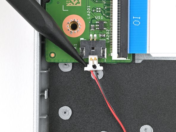
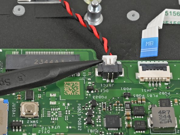
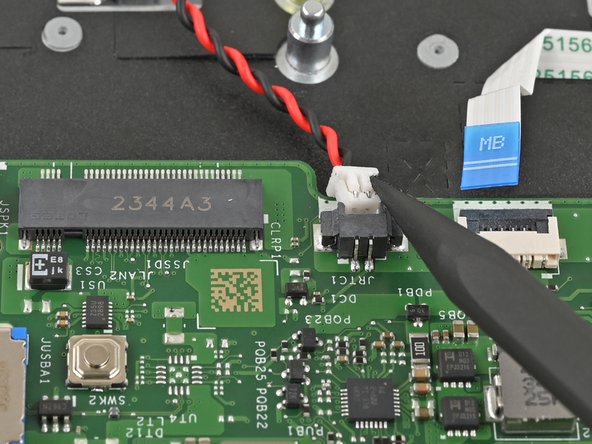
- Use the tip of a spudger to push on either side of the RTC battery cable connector and "walk" it out of its socket.
- This connector can be difficult to loosen. Take your time and work slowly.
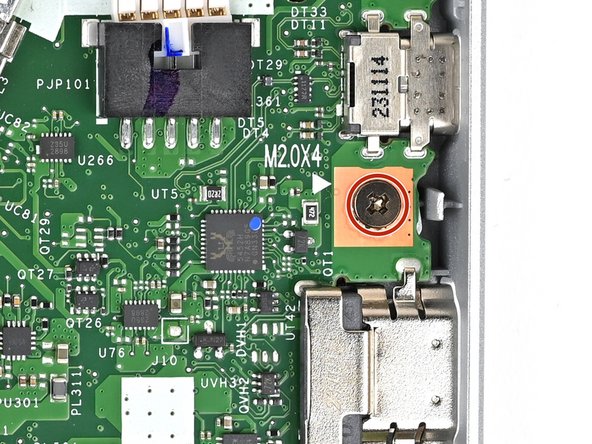
- Use a Phillips screwdriver to remove the 4.7 mm‑long screw securing the motherboard.
- Lift the motherboard out of the frame and remove it.