Drain Pumps for Balay and Bosch Dishwashers
ID: 175488
Description:
Steps:
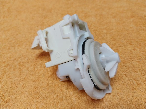
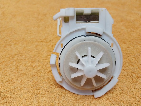
- Example of a drain pump from older BALAY and BOSCH dishwashers (over 10 years old), in which the drain pump was powered directly at 230 V (mains voltage in Spain). A classic question is: what happens in countries with a 110 V power grid? The pump will be a 110 V version, as a 230 V one would not work.
- Photo 1: We see the 2 faston terminals of the coil.
- Photo 2: We see the clip or locking tab of the pump, which ensures that once it is inserted into its housing, it cannot come out on its own. To remove it, you must press this tab and turn it a 1/4 turn to remove the pump.
- Video: An example of a drain pump teardown.
- Video: How to test the drain pump.
- Video: Another video regarding the pump test.
- View of the locking tab; push it with a screwdriver and turn it 1/4 of a turn at a time, then pull the pump out.
- Before connecting the drain pump directly to the electrical mains, it is very important that we check the labeling to see what voltage the pump works at. They do NOT operate at the same voltage in all countries; there are 110 V and 230 V versions.
- Current pumps used in Balay and Bosch dishwashers since approximately 2010, smaller than the previous ones; this one is from a dishwasher purchased in 2012, it is a 55 V three-phase pump, so the electronic board performs the frequency converter function.
- We continue to see on current pumps the locking tab or arrowhead for when the pump is inserted into its housing.
- Detail photo 3, this pump requires 3 phases = 3P = 3 Phase and is 54 V 55 Hz SO WE CANNOT CONNECT IT DIRECTLY TO THE MAINS VOLTAGE.
- Views of the dishwasher drain pump interior.
- As we can see, it is a three-phase pump; it receives 3 wires, has 3 coils connected in a star configuration, and only starts with the voltage and frequency sent by the electronic board.
- Video where we see the pump.
- I have tried to start it to see if it could be tested with a 15-0-15 V dual-output transformer and a capacitor to simulate the 3rd phase, or one with 24 V, WITHOUT SUCCESS; the pump only vibrates and does not spin, so there is no way to test it at home.
- Exploded view of the 3 drain pump windings, as seen they are connected in a star configuration.
- The pump shaft must rotate smoothly and should not show any kind of jamming on its shaft; besides checking this and measuring the 3 coils, which should provide similar readings, we would have no other option but to replace it.
- END of guide.