Battery Revival
ID: 175512
Description: Most "new" old stock backbeat fits suffer from...
Steps:
- First we must check if this device would benefit from battery revival / recharging. Plug in a charger and make sure that the ear piece red lights illuminate. This will indicate that the onboard charger, regulator, and electronics are functioning.
- However, if the unit is incapable of holding a charge, you should see that it will pull no current from the wal-wart charger. Not required, but you can see charging current from a USB power monitor such as the Klein Tool ET920.
- If the red lights do not turn on, then this repair guide will not able to assist you; a deeper level repair is required.
- Identify the left earpiece.
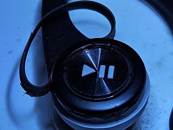
- Stick a dull knife or pointed object under the gasket opposite side of the ear loop.
- Pull back the gasket covering the edge of the pushbutton cover; taking care to not rip or tear the rubber. If glue is holding onto the rubber, use an exacto knife to carefully cut it back.
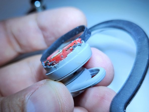
- Carefully separate the glue from the tangs holding the button cover to the battery assembly and outter housing.
- There are four tangs in total, three are easy to access with the gasket out of the way.
- I used an exacto knife, but becareful to not cut any wires coming down from the ear loop, or destroying any of the detents which hold the button cover in place.
- Take your time, the attachment to the battery housing is much stronger than the strength of the plastic cover.
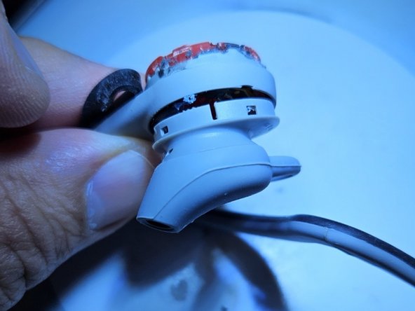
- With the button cover removed, you can run a dull knife down through the sides to free up the glue holding the earpiece to the main housing.
- Apply gentle pressure to pull the earpiece away. Be careful to not rip the very short speaker wires.
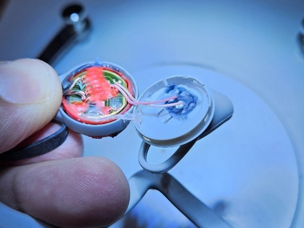
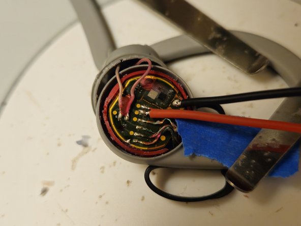
- With the earpiece removed, we can get access to the battery charging terminals. Identify the location of the cell positive and negative terminals.
- The negative terminal (cell ground) is a large soldered tab. The positive terminal is the second lead from the square IC chip.
- Remove the silastic wire bonding to expose the ground and positive lead. De-solder and tape back the cell positive ground to protect the unit's electronics from the charging current in the next step.
- Solder appropriately colored wires on to the two terminals.
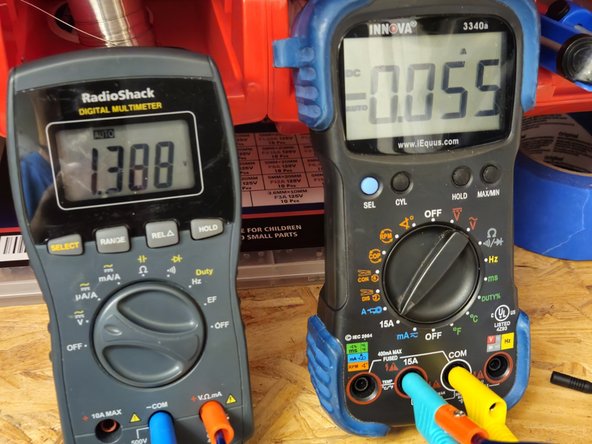
- Check battery voltage, it should be at or near 0V.
- Apply a charging profile consistent with the battery datasheet. Varta CP1654.
- If you lack a battery charger, a low voltage supply through a current limiting resistor can work. Limit charging to 1C rate (<60mA) and increase voltage periodically as battery voltage recovers.
- If the charge voltage does not raise above a 1V in a few minutes, the cell is most likely damaged beyond repair.
- DO NOT APPLY VOLTAGE OR CURRENTS GREATER THAN THAT SPECIFIED IN THE DATASHEET. THIS MAY RESULT IN DAMAGE TO THE CELL, ELECTRONICS, OR PERSONAL INJURY!
- If you do not know how to properly recover the battery, it is recommended that you stop charging at ~3.5V, and allow the onboard charger to complete the rest after re-assembly.
- Solder the positive battery wire back to the second position solder pad.
- Apply glue to cover the exposed wire and ground terminals.
- Continue reassembly in reverse order.
- Once assembly is complete, complete the charging process with the USB cable.
- If you have it, it is recommended to monitor the charge with a USB power meter.
- Note: the battery will require a few deep cycles (empty -> full) to re-stabilize after being drained for an extended period of time.