Disassembling Marshall Stockwell II Portable Bluetooth Speaker
ID: 175575
Description: This is a Bluetooth speaker that can be used...
Steps:
- BUILT FOR LIFE ON THE ROAD, THIS COMPACT PORTABLE SPEAKER OFFERS 20 + HOURS OF PLAYTIME.
- Echoing the legacy of rock ‘n’ roll, Stockwell II has a solid metal grille that pays homage to the steel mesh grille found on many microphones and a guitar inspired carry strap for easy portability.
- Its roadworthy construction with silicone exterior and IPX4 waterresistant rating make it extremely rugged and durable.
- Total weight: 1400g
- Length: 161mm
- Width: 70mm
- Height: 180mm (without carrying strap)
- Remove the handle by unscrewing the visible gold screws on each side and remove the gold shims by hand, like undoing a button. The back of the black carrying strap is made of a light brown material that resembles tumbleweed, according to the literature, all Marshall products are vegan-friendly; only leather-like material is used. https://www.marshall.com/sg/en/product/1...
- The device has a carrying strap for easy carrying. It consists of a black carrying strap(22g) and two gold irregular spacers(Less than 1g) and is attached to the body by round head screws(Less than 1g) on both sides.
- Gasket height: 9mm
- Gasket width: 13mm
- Screw diameter: 4mm & Thread length: 9mm
- Carrying strap lengths: 400mm
- Carrying strap thickness: 4.5mm
- Carrying strap width: 34mm
- According to the information"Stockwell II’s roadworthy construction with silicone exterior also has an IPX4 water-resistance rating, so it can withstand splashes of water when the weather starts to turn."
- Remove the outer rubber by hand(It may also be made of synthetic rubber)
- Rubber sleeve weight: 100g
- Length: 147mm
- Width: 67mm
- Height: 171mm
- The front cover(60g) consists of a dust cloth made of black metal mesh and black translucent soft fabric with black sponge tape glued around the lining.
- Use a pry bar or one screwdriver to open it along the edge. You can find 11 non-removable rivets on the back holding the logo. Use Flat Needle Nose Pliers to break off the rivets and remove the logo.
- Panel length: 131mm
- Panel width: 151mm
- Panel thickness: 12mm
- Logo length 75mm & width: 20mm
- Logo spacer length: 75mm & width 17mm
- You need wear rubber insulating gloves for this step.
- Remove the screws and take off the battery cover(9g). The screws attaching the cover are two black flathead flat tip screws. Disconnect the battery(5-pin). This step does not remove the battery.
- Battery cover length: 113mm
- Width: 36mm
- Height: 12mm
- Screw diameter: 2.6mm
- Thread length & Thread quantity: 4mm & 4
- Head diameter:4.8mm
- Remove and sort the front panel screws (×8) and the front paper cone full-range speaker screws (×4). After measuring the two screws are the same size both are round head and flat tip screws.
- Screw diameter: 3mm
- Thread length & Thread quantity: 9mm & 9
- Head diameter:5mm
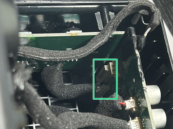
- Disconnect the top control panel from the right control panel
- Remove the right main control board module by hand vertically upwards, this control board is removed from the charging control board below.
- Let's remember where each wire is connected.
- Connect to the top control board
- Bluetooth signal cable
- Front and back paper cone full-range speaker connections. Note: The control panel is labeled "REAR" (2pin) and "FRONT" (3pin).
- Thin Series Wooferconnect(2pin)
- Cables for connecting the battery
- This step allows us to take out the battery and the main control board for the stereo. And you can clearly see the internal layout.
- This is the front cover that contains a small front-facing speaker and a large speaker inside.
- The main body contains many things within it. This is where the battery and battery compartment are located.
- The main control board is plugged vertically into the charging control board. The main control panel and top switch assembly, the battery, and each speaker connection are connected by wires.
- This is the small speaker location on the back and the top switch control assembly.
- Battery weight: 93g/ Length 71mm/ Width: 40mm/Thickness: 20mm
- Main control board weight: 49g / length 134mm / width: 57mm
- You need gloves for this step. Involves black soft rubber and sharp-edged items
- Remove the soft black gel from the paper cone fullrange speaker by hand and remove the paper cone fullrange
- Remove the four screws from the thin series woofer and remove the thin series woofer.
- Round head and flat tip screws(x4)/ Head diameter:5mm
- Thread length & Thread quantity: 9mm & 9
- Screw diameter: 3mm
- The front panel is mainly divided into the housing(126g), the paper cone fullrange(93g) and the thin series woofer(159g)
- Length: 143mm
- Width: 166mm
- Height (highest point): 45mm
- Paper cone fullrange length and width: 55mm
- Height: 33mm
- Thin series woofer length and width: 80mm
- Height: 28mm
- You need gloves for this step. Involves black soft rubber and sharp-edged items
- Remove the back grill(63g) as you would the front grill.
- Unscrew the four screws of the paper cone fullrange and clean the black fixing and remove the paper cone fullrange
- Unscrew the four screws and remove the thin series woofer rear plate protection
- The back stencil is slightly larger than the front. A mesh cover made of iron, lined with a translucent-like dust cloth and sponge tape around the edges.
- Length: 156mm
- Width 134mm
- Height/thickness: 11mm
- Paper Cone Fullrange(93g) size of the rear (2pin) Length/Width: 55mm
- Height: 33mm
- There is a spacer on the back of the series woofer that acts as a protector(39g), It's made of what looks like synthetic rubber, and it's encased in metal. And there is also a fragile edge spacer made of sponge.
- Diagonal distance: 90mm
- Diameter: 78mm
- Thickness: 4mm
- The screws for the speaker and gasket are the same screws, both round head, flat tip screws Head diameter:5mm
- Thread length & Thread quantity: 9mm & 9 / Screw diameter: 3mm
- This step disassembles the charging port control board. Start by disconnecting the 2pin wire to the top panel control board.
- Then unscrew the two fixing screws and remove them, they are round heads and flat-tip screws
- Screw diameter: 2mm
- Thread length: 7mm
- The whole of removing the charging port (9g) is divided into three parts, the main panel, the charging port rubberised case and the main body case.
- Length: 53mm/Width: 18mm/Weigh: 6g
- Length: 52mm/Weigh 1.5g
- Width: 17mm
- Height: 12mm
- Length: 31mm/Weigh: 1.5g
- Width: 16mm
- Height: 12mm
- In this step, we will take out the top part. Pull out the top whole in the direction of the arrow
- This gives us a completely stripped-out enclosure and a top switch control section.
- Length: 166mm
- Width: 145mm
- Height: 55mm
- Weigh: 245g
- Pull the cap off by hand or with the help of a tool.
- Unscrew the four screws on the top control panel.
- Four round head flat tip screws
- Thread length: 7mm
- Screw diameter: 2mm
- Weigh: 1g
- Bottom Diameter: 17mm
- Height: 14mm
- You can unscrew the three hexagonal nuts by hand or with the help of a tool. Unscrewing these three final screws means that the entire section will be completely separated.
- After this step of disassembly it means that all of our disassembly is complete. The top section mainly consists of the switch control motherboard, iron spacer, rubber button sleeve, housing, nut to hold the switch and finally the cap.
- Length of top housing long side: 127mm
- Short side length: 124mm
- Width: 47mm
- Height: 20mm/Weight: 26g
- Hexagonal nut diameter on opposite side: 10mm/Weight less than 1g
- Inner ring diameter: 6mm/Thickness: 2mm
- Rubber gasket Outer ring diameter: 12mm
- Inner ring diameter: 7mm/Thickness: less than 1mm
- Outer ring diameter: 12mm
- Inner ring diameter: 7mm
- Length: 21mm/Weight less than 1g
- Width: 17mm
- Height: 15mm
- Length: 111mm/Weight: 34g
- Width: 40mm
- This bluetooth stereo is completely removable
- The key screws in several parts of the device are of the same type and can be purchased if the screws are lost.
- The battery is replaceable but requires a 5pin connector to connect.