Kambrook Blitz 2 Go Teardown
ID: 175737
Description: A step-by-step guide on how to disassemble a...
Steps:
- Cup lid height (excluding blade): 40mm
- Bottle height: 250mm (600 ml)
- Blender main body height: 78mm
- Cup lid diameter:75mm
- Bottle diameter: 79mm
- Blender main body diameter: 127mm
- The bottom of this blender has four rubber bases to help prevent slipping and stabilize the device when it is stationary and working. These four rubber bases can be easily pulled out with your fingers.
- There are two phillips screws inside the round hole. Use a Phillips screwdriver to remove them
- There are two special screws in the two round holes. If forced disassembly is allowed, the base can be opened by using an electric drill to destroy the two screws.
- Length of rubber sole: 40mm
- Width of rubber sole: 7mm, Weight: 4.8g
- SS Philips screw diameter: 5.2mm
- SS Philips screw length: 10mm, Weight: <1 g
- Rubber is made by liquefying rubber and injecting it into a mold of a specific shape and cooling it. The manufacturing process of stainless steel screws is divided into four steps: cold heading, heat treatment, turning and grinding.
- The blender can be further disassembled after being opened from the base. Two SS Phillips screws are holding the film capacitor to the base.
- Two SS Phillips screws fix the cord to the base through a PC cable clip to avoid large movement of the cord.
- With further disassembly you can get a SRCAP film capacitor+circuit board, SS Phillips screw x4 and a PC cable clip.
- Length of the SRCAP film capacitor+ circuit board:31mm
- Height of the SRCAP film capacitor+ circuit board: 17mm
- Width of the SRCAP film capacitor+ circuit board: 16mm, Weight: 6g
- The manufacturing process of film capacitors: making dielectric film, winding the film onto a cylindrical core, and finally encapsulating it in a casing.
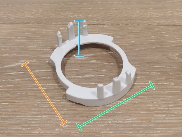
- Width of PC cable clip: 6mm
- PC cable clip length: 22mm
- Diameter of the SS Phillips screw X4: 5.2mm
- Length of the SS Phillips screw X4: 10mm
- Manufacturing process of PC cable clip: Injection molding.
- Weight of PC cable clip: < 1g
- Disassemble the three circled SS phillips screws in the red area using a Phillips screwdriver.
- After disassemble the screws, shake the black ABS switch base to disassemble all the parts of the switch.
- The switch part includes: Black ABS switch base x1, SS Philips screw x3, ABS Switch button x1, SS Spring x2 and PC component x1.
- This black ABS switch base can be fixed inside the blender by forming a part with the PC component and fixing it with a SS Philips screw.
- These three SS Phillips screws are the same size as the SS Phillips screws in the previous steps.
- This is a ABS switch button that users can see on the outside of the blender. This ABS switch button is connected to the black ABS switch base and the PC component through two SS springs to form a mechanism. Users can control the electric machine inside the blender to turn on and off by pressing the switch button from the outside.
- Diameter of SS spring: 7mm
- Length of SS spring: 15mm, Weight: 5.5g
- SS spring manufacturing process: Cold forming, crimp forming and cutting.
- The function of the spring is to return the pressed switch button to its original position and to displace the PC component to control the electric machine to open and close.
- Length of black ABS switch base: 55mm, Width: 35mm, High: 26mm, Weight: 7g
- The manufacturing process of black ABS switch base: Injection molding.
- The manufacturing process of ABS switch button: Injection molding.
- Diameter of switch button: 35mm, High: 25mm, Weight: 3g
- Length of PC component: 90mm, Width: 21mm, High: 12mm, Weight: 3g
- The manufacturing process of PC component: Injection molding.
- So far the blender has been disassembled into three parts. What we are going to do next is to separate these three parts into independent parts.
- Choose a screwdriver of appropriate size and insert it into the gap inside the electric machine to stop the electric machine from turning.
- After that, turn the device upside down, and you will see a black component that you can use pliers to hold it and turn it to remove it.
- There is a base under the electric machine to connect the electric machine to the top housing of the blender.
- First use a Phillips screwdriver to disassemble the three Phillips screws to separate the electric machine and base from the top housing of the blender.
- Then disassemble the Phillips screws on the back of the base to separate the base from the electric machine.
- These two Phillips screws are the same as the yellow ones, but after many attempts, they were still very difficult to disassemble, so I destroyed them with a power drill.
- By disassembling these two Philips screws, the electric machine can be separated into an outer electric machine and an inner electric machine. When the electric machine is powered on, it rotates through the interaction of these two groups.
- The main part of the blender has been completely dismantled.
- The main shell of the blender is made of ABS injection molding, and then the color of the appearance is changed to silver through electroplating. This gives a nice metallic look.
- Length of the main shell: 130 mm
- Width of the main shell: 130mm
- High of the main shell: 123mm, Weight: 89g
- The top shell of the blender is made of HIPS injection molding, which can be used to assemble the part of the switch button and the part of the electric machine.
- High of the top shell: 135mm
- Diameter of the top shell: 95mm, Weight: 74g
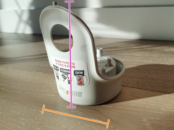
- The bottom shell of the blender is made of PP injection molding, which material is lightweight, uncorroded by chemicals such as acids, alkalis and salts, and is impact and fatigue resistant. It can protect the electric machine and discharge the heat generated by the electric machine outside the machine.
- Length of bottom shell: 127mm
- Width of bottom shell: 127mm
- High of bottom shell: 100mm, Weight: 93g
- The electric machine base is made of polyamide 66 injection molding. It connects the electric machine to the top housing of the blender.
- Length of the electric machine base: 80mm
- Width of the electric machine base: 85 mm
- High of the electric machine base: 50mm, Weight: 22g
- The rotor in the electric machine is manufactured through processes such as casting, forging, turning, grinding and dynamic balancing. It is made of metal materials, carbon fiber composite materials and rare earth permanent magnet materials. The function of the rotor is to generate torque and induced electromotive force for the electric machine.
- Rotor diameter: 55mm
- Length of rotor: 125mm, Weight: 191g
- SS Piliphs screw, which function is to assemble the rotor and electric machine.
- Length of SS Piliphs screw: 47mm
- Diameter of SS Piliphs screw: 8mm, Weight: 4.2g
- The manufacturing process of rubber pads is to melt the rubber by heat, then inject it into the mold and cool it to form, which function is cushions the electric machine base and electric machine to reduce friction and vibration.
- Length of rubber pads: 35mm, Width: 27mm, Weight: <1g
- This is a black PCM (post-consumer-material) component, which manufacturing process is injection molding, and the function of it is the rotating force of the rotor drives the component of the cup cover to stir things.
- Diameter of the black PCM component: 30mm
- High of the black PCM component: 12mm, Weight: 6g
- Diameter of the SS Philips screw: 10mm
- Length of the SS Philips screw: 10mm, Weight: <1g
- Diameter of the SS Philips screw: 6mm
- Length of the SS Philips screw: 11mm, Weight: <1g
- The manufacturing process of epoxy resin gasket is casting molding, and the function of it is include insulation, thermal resistance, chemical resistance, mechanical and node performance. It has an anti-vibration effect and can reduce vibration and noise during equipment operation
- Diameter of epoxy resin gasket: 17mm, Weight: <1g
- Same as red.
- Diameter of epoxy resin gasket: 15mm, Weight: <1g
- The manufacturing process of stainless steel gaskets is stamping, which has the functions of sealing, supporting, adjusting gaps, anti-slip, and anti-corrosion.
- Diameter of SS gasket:11mm, Weight: <1g
- Same as red and oringe.
- Diameter of epoxy resin gasket: 13mm, Weight: <1g
- First, secure the bottle cap.
- Use pliers to clamp a blade.
- Use another pair of pliers to hold the black component and rotate it.
- The nut will be disassemble along with the black component.
- Use a screwdriver to press the circled position and pull out the white component.
- The bottle cap is made of ABS injection molding. Its function is to seal something of the bottle to prevent spillage.
- Diameter of the bottle cap: 75mm
- High of the bottle cap: 36mm, Weight: 56g
- This is a POM spacer component, which is manufactured by injection molding, and its function is to further seal the bottle cap to prevent liquid from spilling.
- Length of spacer component: 66mm
- Width of spacer component: 60mm
- High of spacer component: 26mm, Weight: 9g
- This is a black PA component. Its manufacturing process is injection molding. Its function is to overlap with the PCM component on the blender and be carried by it to rotate. Diameter of the PA component: 27mm, High: 10mm, Weight:<1g
- This is a SS blade, which is made by cutting molding, and the function of its is to crush the something of the bottle.
- Diameter of the blade: 55mm
- Length of blade: 40mm, Weight: 13g
- This is an aluminum nut, which is made by cold heading. Its function is to fix the blade and the black PA component to the bottle cap.
- Length of AL nut: 9mm
- Width of AL nut: 9mm
- High of AL nut: 4mm, Weight: <1g