Samsung Galaxy S24 Ultra Front Camera Replacement
ID: 175795
Description: Use this guide to replace the front camera in...
Steps:
- Allow your phone's battery to drain below 25%, as a charged lithium-ion battery is a potential safety hazard. If your battery is swollen, take appropriate precautions.
- Unplug any cables from your phone.
- Hold the side key and the volume down button, then select "Power off" to turn off your phone.
- Heat an iOpener and apply it to the right edge of the back cover for two minutes.
- You may use a hair dryer, heat gun, or hot plate instead, but be careful not to overheat the phone—the display and internal battery are susceptible to heat damage.
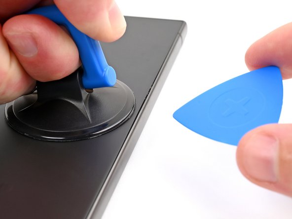
- Apply a suction handle to the back cover, as close to the center of the right edge as possible.
- Pull up on the suction handle with strong, steady force to create a gap between the cover and the frame.
- If you have trouble creating a gap, apply more heat to further soften the adhesive. Follow the iOpener instructions to avoid overheating.
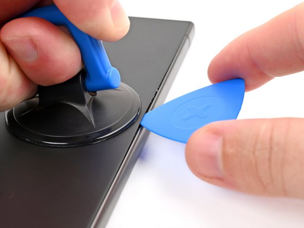
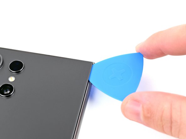
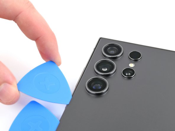
- Insert an opening pick into the gap.
- Slide the pick back and forth along the right edge to separate the adhesive.
- Leave the pick inserted near the bottom right corner to prevent the adhesive from resealing.
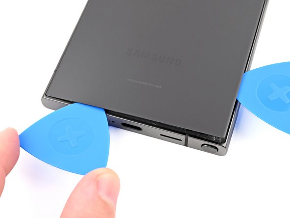
- Apply a heated iOpener to the bottom edge of the back cover for two minutes.
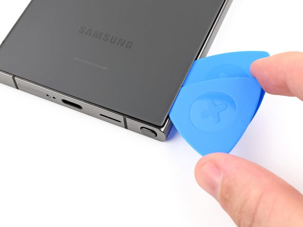
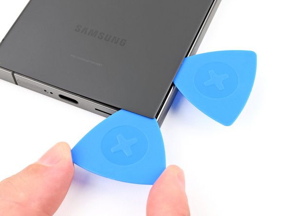
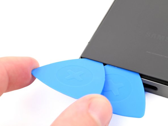
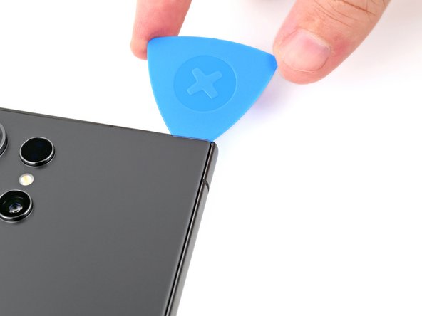
- Insert a second opening pick next to the first one, near the bottom of the right edge.
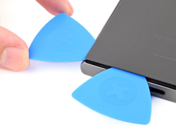
- Rotate the opening pick around the bottom right corner to separate the adhesive.
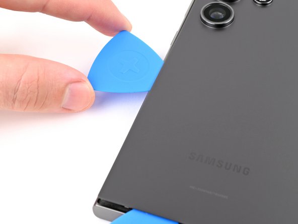
- Slide the opening pick along the bottom edge to separate the adhesive.
- Leave the pick inserted near the bottom left corner to prevent the adhesive from resealing.
- Apply a heated iOpener to the left edge of the back cover for two minutes.
- Insert a third opening pick next to the second one, near the left side of the bottom edge.
- Rotate the opening pick around the bottom left corner to separate the adhesive.
- Slide your opening pick along the left edge to separate the adhesive, stopping before you reach the power button.
- Do not insert the pick more than 4 mm to avoid damaging the antenna cable.
- Leave the pick inserted near the power button to prevent the adhesive from resealing.
- Apply a heated iOpener to the top edge of the back cover for two minutes.
- Insert an opening pick in the gap at the top of the right edge.
- Rotate the opening pick around the top right corner to separate the adhesive.
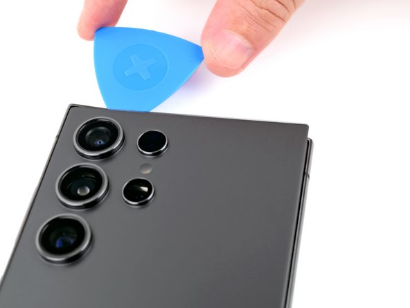
- Slide the pick along the top edge to separate the adhesive.
- Do not insert the pick more than 4 mm to avoid damaging the sensor or camera near the top edge.
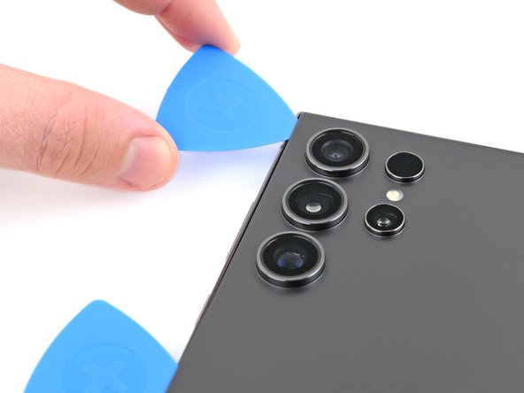
- Slide the pick around the top left corner and down the left edge to separate the remaining adhesive.
- Do not insert the pick more than 4 mm to avoid damaging the cameras.
- Grab and remove the back cover.
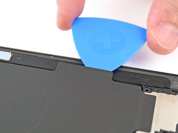
- If your cover is still sticking to the frame, slide an opening pick around the edges to separate any adhesive that may have resealed.
- During reassembly:
- This is a good point to power on your phone and test all functions before sealing it up. Be sure to power your phone back down completely before you continue working.
- Remove any adhesive chunks with a pair of tweezers or your fingers. Apply heat if you're having trouble separating the adhesive.
- If you're using custom-cut adhesives, follow this guide.
- If you're using double-sided tape, follow this guide.
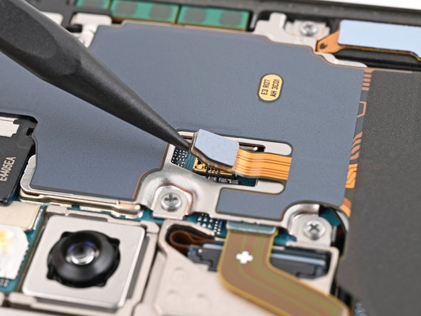
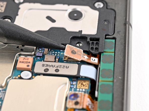
- Use a spudger to pry up and disconnect the wireless charging coil press connector from the motherboard.
- There's an arrow printed on the board near each press connector that indicates the recommended prying location. Only pry in this location for each press connector to avoid dislodging surface-mounted components.
- To reconnect press connectors, align the connector carefully over its socket and press down with your fingertip—first on one side, then the other—until it clicks into place. Don't try to force the connector into place. If you're having trouble, reposition it and try again.
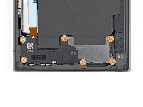
- Use a Phillips screwdriver to remove the ten 3.5 mm‑long screws securing the wireless charging coil and the loudspeaker:
- Four screws securing the wireless charging coil
- Six screws securing the loudspeaker
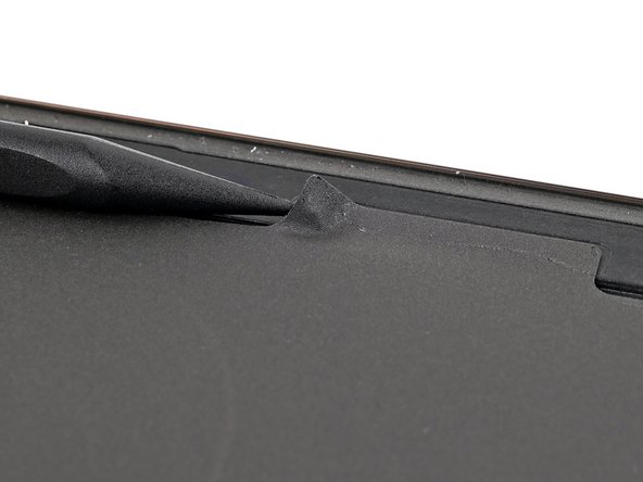
- Use a spudger to gently pry up a corner of the tab of the wireless charging coil that's adhered to the right edge of the frame.
- Use an opening pick to separate the tab from the frame.
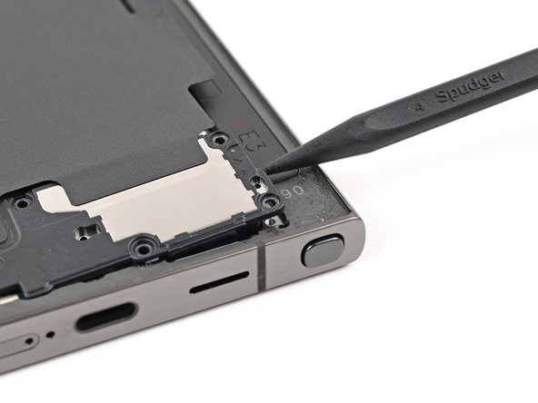
- Insert the point of a spudger into the gap between the right edge of the loudspeaker and the frame.
- There's an arrow engraved in the loudspeaker to indicate the recommended prying location.
- Pry up to unclip the loudspeaker from the frame.
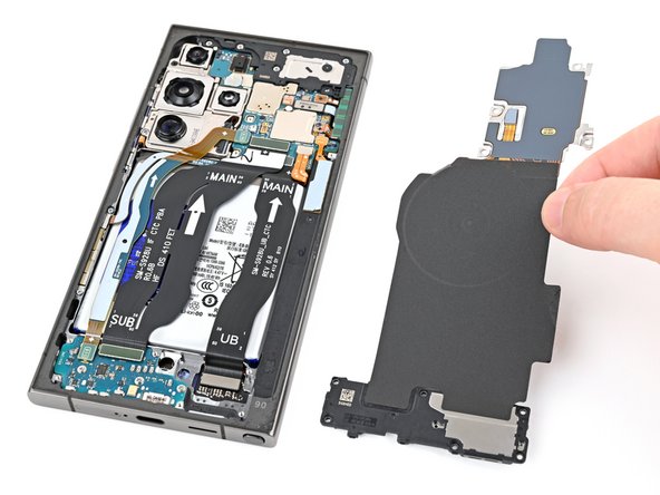
- Remove the wireless charging coil and loudspeaker from the frame.
- During reassembly, press around the edges of the loudspeaker to clip it to the frame before reinserting the screws.
- Use a spudger to pry up and disconnect the battery press connector.
- Use a spudger to pry up and disconnect the earpiece speaker press connector.
- Use a Phillips screwdriver to remove the five 3.5 mm‑long screws securing the earpiece speaker.
- Insert the pointed end of a spudger under the bottom edge of the earpiece speaker, under the engraved arrow.
- Pry up with the spudger to unclip the speaker and remove it.
- During reassembly, insert the top edge of the earpiece speaker into the frame first before pressing down and clipping it back in.
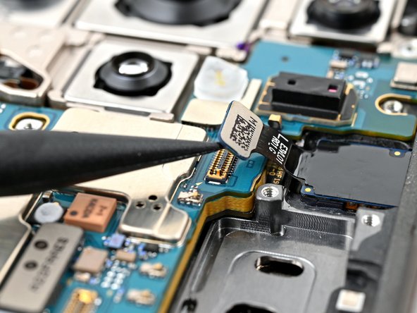
- Use a spudger to pry up and disconnect the front camera press connector.
- Flip the phone over so the screen is facing up.
- Heat an iOpener and apply it to the top edge of the screen for two minutes to loosen the front camera adhesive.
- You may alternatively use a hair dryer, heat gun, or hot plate, but be careful not to overheat the phone—the display and internal battery are susceptible to heat damage.
- Flip the phone back over so the back of the front camera is accessible.
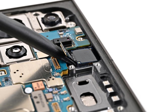
- The adhesive securing the camera is very strong. Work slowly and apply more heat if the front camera feels stuck. Avoid separating the sensor from the lens, such as this.
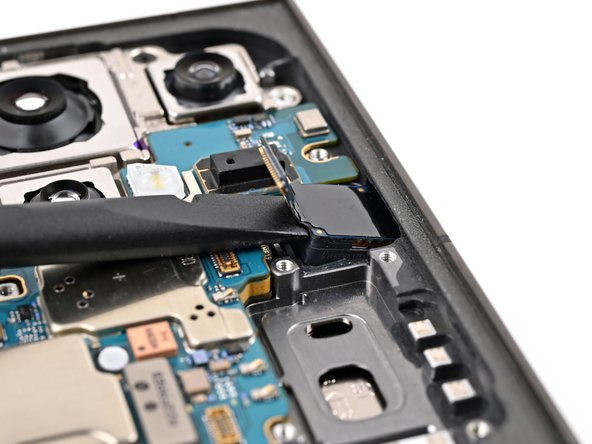
- Use the flat end of a spudger to pry the front camera from its recess in the frame.
- If the camera doesn't loosen, use a SIM eject tool to scrape away the epoxy surrounding the camera.
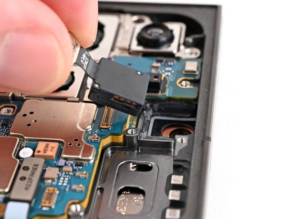
- Lift and remove the front camera.