Google Pixel 9 Pro Rear Cameras Replacement
ID: 175813
Description: This repair guide was authored by the iFixit...
Steps:
- Let your Pixel's battery drain below 25% before starting this repair. A charged lithium‑ion battery may catch fire if damaged.
- Unplug all cables and completely power down your phone.
- Adhesive secures the perimeter of the rear cover to the frame.
- When separating the adhesive, don't insert your tool more than 3 mm under the rear cover to avoid damaging the internal components.
- Measure 3 mm from the tip and mark your opening pick with a permanent marker. Alternatively, you can tape a coin to a pick 3 mm from the tip.
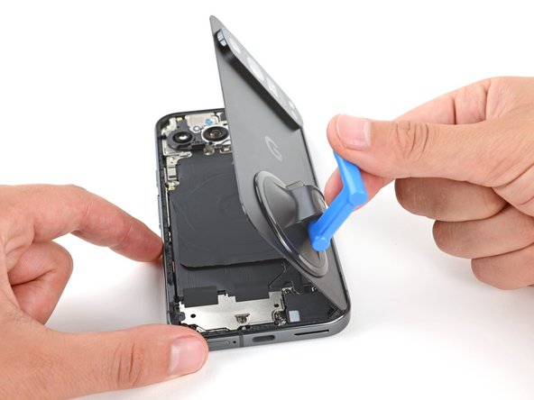
- Attach a suction handle to the bottom edge of the rear cover, as close to the edge as possible.
- Pull up on the suction handle with strong, steady force to create a small gap under the rear cover.
- Insert the tip of an opening pick in the gap.
- Slide your opening pick along the bottom edge to separate the adhesive securing it.
- Remember: don't insert the opening pick deeper than 3 mm.
- Slide your opening pick up the left edge and along the top edge to separate the adhesive.
- Slide your pick down the right edge to separate the remaining adhesive.
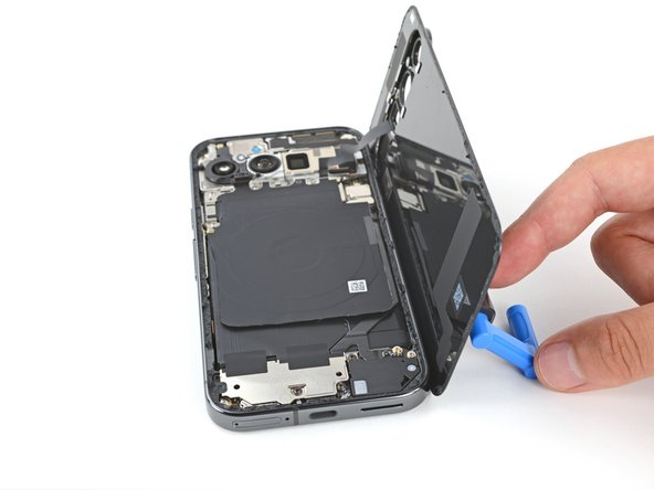
- Don't try to fully remove the rear cover yet, as a ribbon cable on the right edge connects it to the phone.
- Use the suction handle to lift the left edge of the rear cover and swing it over the right edge, like opening the cover of a book.
- If you're having trouble, check the perimeter for any remaining adhesive and use your opening pick to separate it.
- Prop up the rear cover with the suction handle so you can access the ribbon cable near the top right corner.
- Throughout this repair, keep track of each screw and make sure it goes back exactly where it came from.
- While the Pixel 9 Pro uses Torx Plus screws, standard Torx bits will also work. Make sure to apply constant, downward force to prevent stripping.
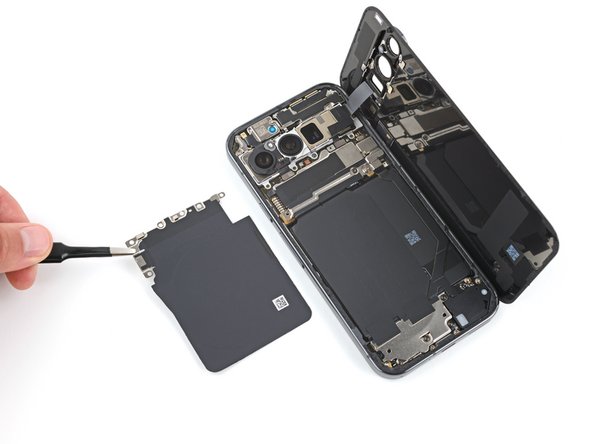
- Use a Torx Plus 3IP screwdriver to remove the five screws securing the wireless charging assembly:
- Four 5.4 mm‑long screws
- One 1.5 mm‑long screw
- This screw is non‑magnetic—you may need to use tweezers to remove it.
- Be very careful not to damage the spring contacts under the top left edge of the wireless charging assembly.
- Use tweezers or your fingers to remove the wireless charging assembly.
- Insert the tip of an opening pick under the left edge of the rear cover press connector and pry straight up to disconnect it.
- Remove the rear cover.
- During reassembly, follow this guide to apply new adhesive and install your rear cover.
- Use a Torx Plus 3IP screwdriver to remove the two screws securing the cable cover:
- One 2.3 mm‑long screw
- One 5.4 mm‑long screw
- Use tweezers or your fingers to remove the cable cover.
- Insert the point of a spudger under the right edge of the battery press connector and pry straight up to disconnect it.
- Use a Torx Plus 3IP screwdriver to remove the 5.4 mm‑long screw securing the mmWave antenna cover.
- Insert the point of a spudger under the clip near the bottom left corner of the mmWave antenna cover and pry up to unclip it.
- Gently pull the right edge of the cover towards the bottom of the phone and remove the cover.
- During reassembly, insert the two tabs on the top corners under their recesses in the frame and push the cover down to clip it into place.
- Use the point of a spudger to pry up and disconnect the mmWave antenna press connector from the top right corner of the logic board.
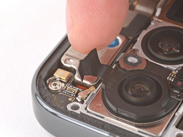
- Use the point of a spudger to pry up and disconnect the front facing camera press connector.
- Be very careful not to touch the cameras during this step. If you accidentally do, wipe them with a clean microfiber or lint‑free cloth.
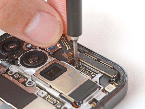
- Carefully hold the front facing camera cable out of the way so you can access the mmWave antenna screw.
- Use a Torx Plus 3IP screwdriver to remove the 4.3 mm‑long screw securing the mmWave antenna.
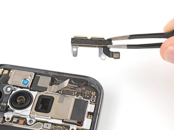
- Use tweezers or your fingers to remove the mmWave antenna.
- During reassembly, make sure the mmWave antenna goes under the front facing camera cable.
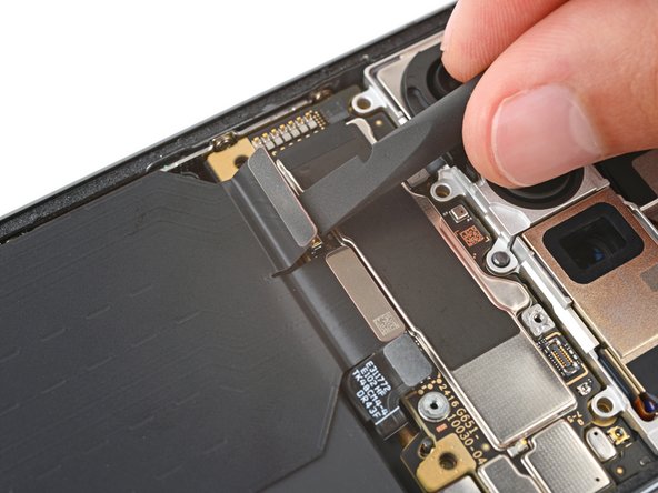
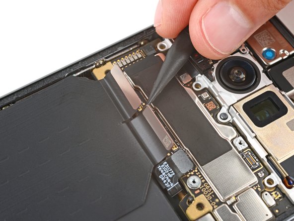
- Use the flat end of a spudger to pry up and disconnect the press connector near the bottom left corner of the logic board.
- Use the point of a spudger to disconnect the press connector just to the right of the previous one.
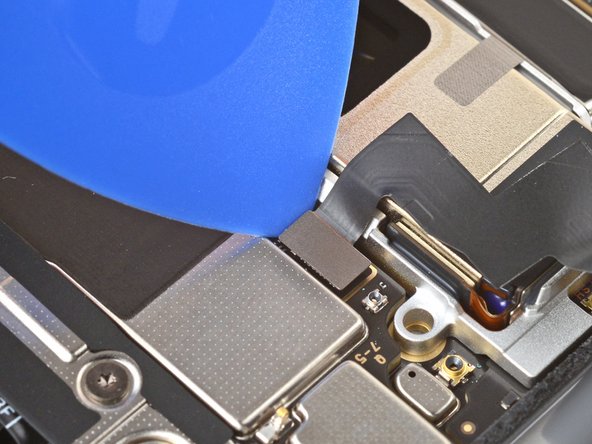
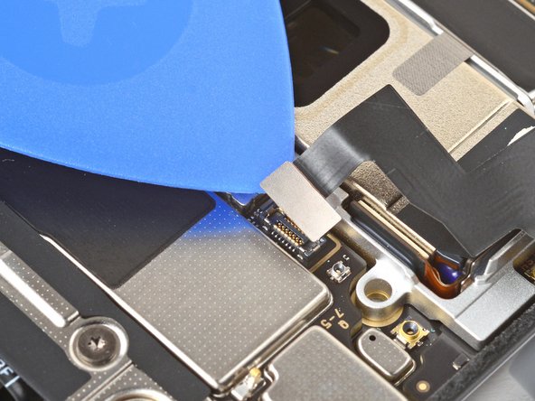
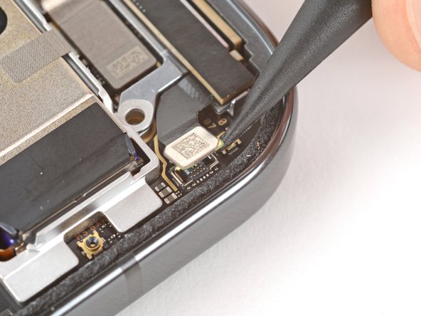
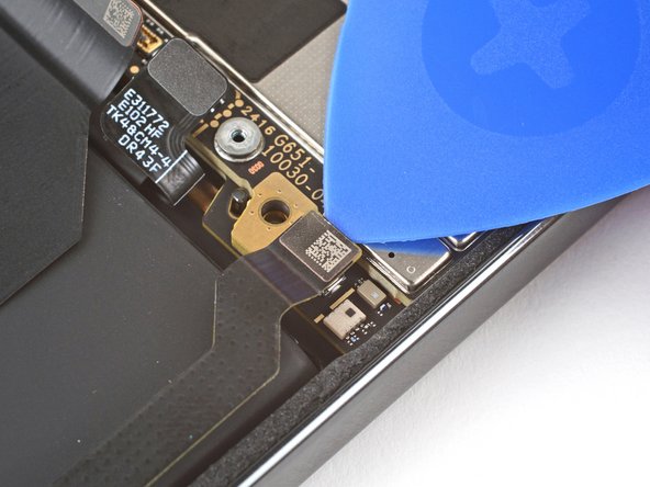
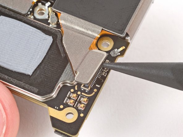
- Insert the tip of an opening pick under the top edge of the press connector near the bottom right corner of the logic board.
- Be very careful not to damage the small, surface-mounted components to the right of the connector.
- Use the pick to pry up and disconnect the press connector.
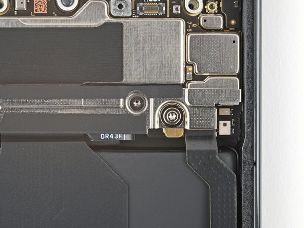
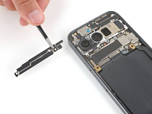
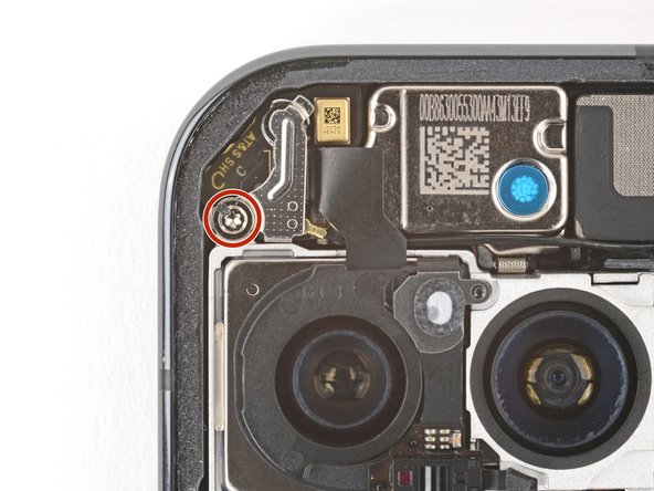
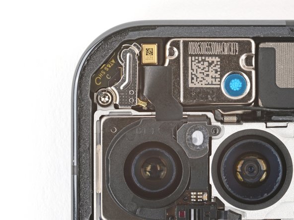
- Use a Torx Plus 3IP screwdriver to remove the 5.4 mm‑long screw securing the antenna cover in the top left corner.
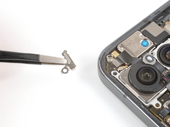
- Use tweezers or your fingers to remove the cover.
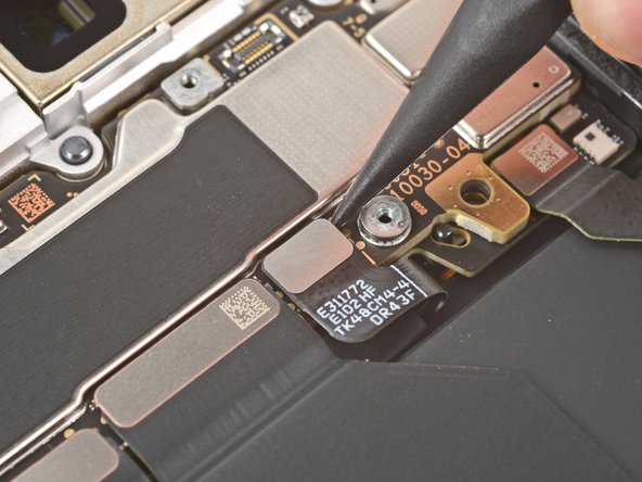
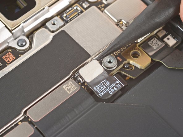
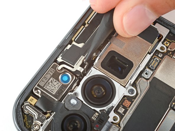
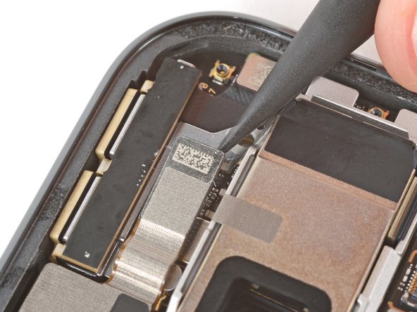
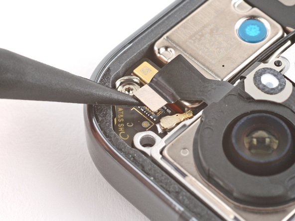
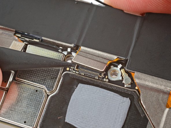
- Use the point of a spudger to pry up and disconnect the autofocus sensor press connector from the top left corner.
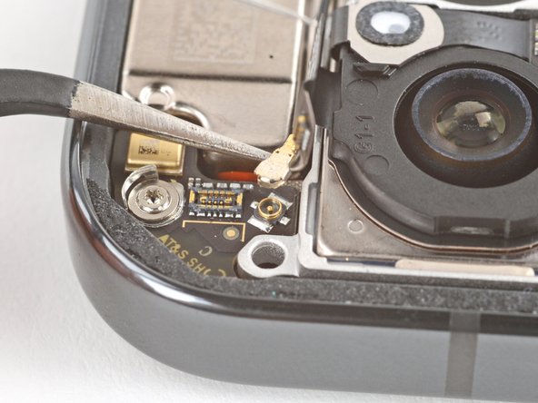
- Carefully move the cable out of the way so you can access the metal antenna connector underneath.
- Slide one arm of your angled tweezers under the metal neck of the antenna connector and lift straight up to disconnect it.
- To reconnect, hold the connector in place over its socket and gently press down with your finger or a spudger—the connector should "snap" into place. If you're having trouble, reposition the head and try again.
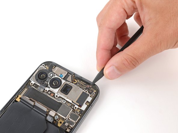
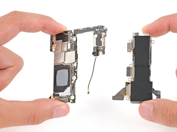
- Use a spudger to pry up the top edge of the logic board until you can grip it with your fingers.
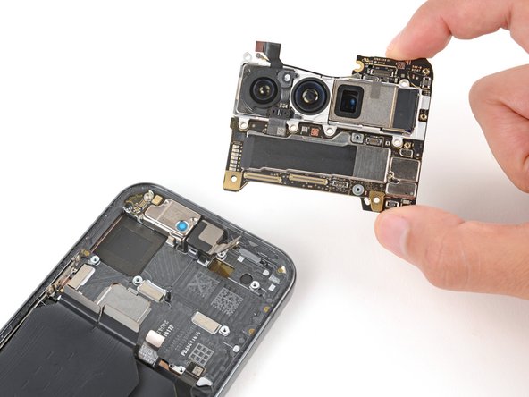
- Grip the right side of the logic board and carefully remove it, being careful that no cables get snagged (one front facing camera cable and four cables along the bottom edge).
- During reassembly, hold the front facing camera cable out of the way and lower the logic board into place, making sure the four cables along the bottom edge don't get trapped underneath.
- During reassembly:
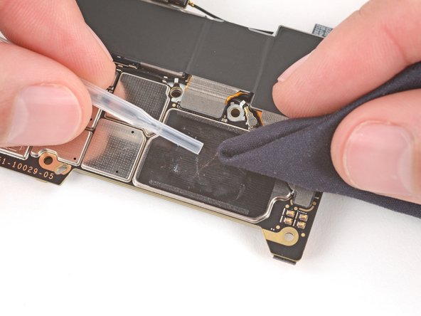
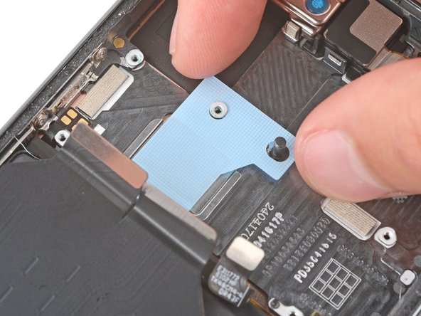
- Check the condition of the logic board thermal pad—it will either be on the bottom of the logic board or on the frame.
- If the pad is undamaged, skip the rest of this step.
- If the pad is damaged, use the flat end of a spudger to scrape it up and remove it.
- Use isopropyl alcohol (greater than 90%) and a microfiber cloth to remove all thermal pad residue from the frame and bottom of the logic board.
- Apply a new thermal pad to its spot on the frame.
- Be very careful not to damage any of the small, surface‑mounted components when disconnecting the cameras in the next two steps.
- Hold the logic board above your work surface while disconnecting the rear cameras—don't press the board against your work surface, or you may damage fragile components.
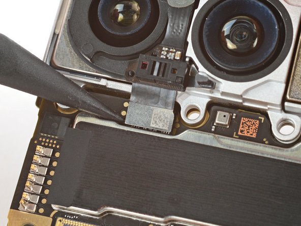
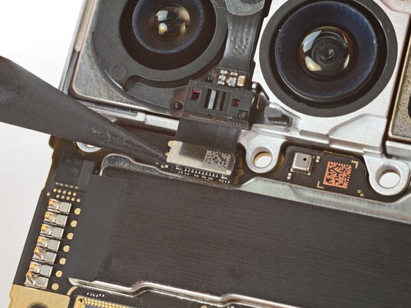
- Use the point of a spudger to pry up and disconnect the autofocus sensor press connector on the top of the logic board, near the left edge.
- Carefully flip the logic board over so the bottom is facing up.
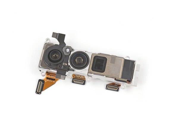
- Use the point of a spudger to pry up and disconnect the three camera press connectors.
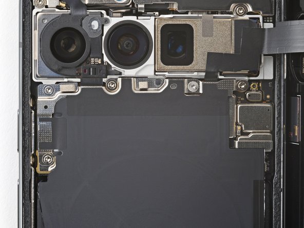
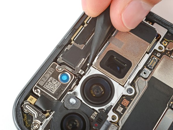
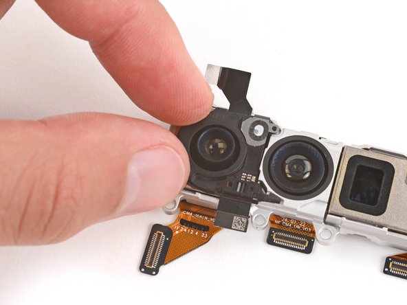
- Hold the logic board in one hand, and use your free hand to gently remove the rear cameras.
- During reassembly, make sure the three camera cables go on the underside of the logic board and the autofocus sensor cable goes on top.
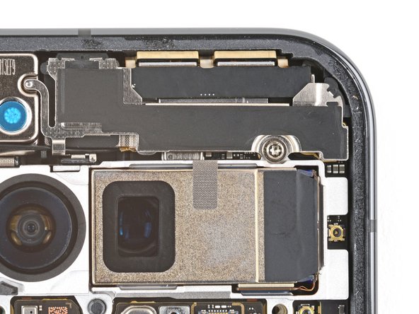
- Check if there's an autofocus sensor pre‑installed on the top of your replacement rear cameras. If there isn't, follow the remaining steps to remove and transfer the sensor from your old cameras.
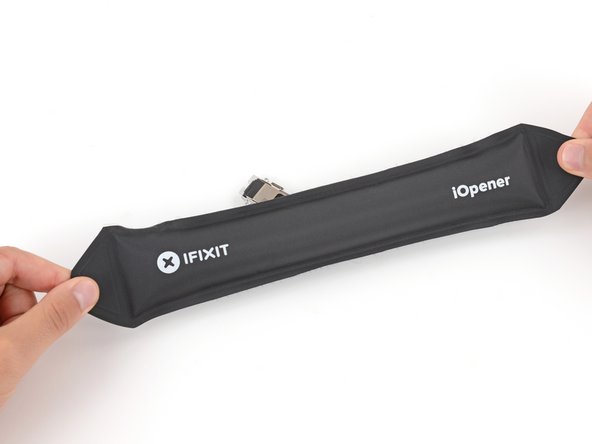
- Apply a heated iOpener to the top of the rear cameras to heat the adhesive securing the autofocus sensor.
- Alternatively, you can lightly heat the sensor with a hair dryer—be careful not to overheat the sensor, as the plastic can warp.
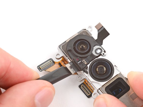
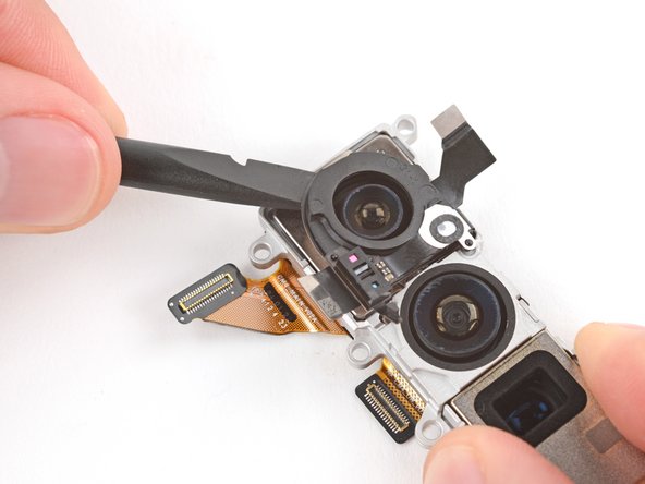
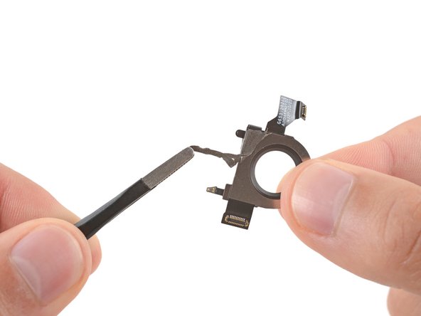
- Gently slide the flat end of a spudger under the bottom right corner of the autofocus sensor (near the cable) to begin separating the adhesive.
- Continue sliding the spudger under the perimeter of the sensor to separate the remaining adhesive.
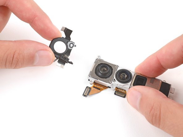
- Use your fingers to remove the autofocus sensor.
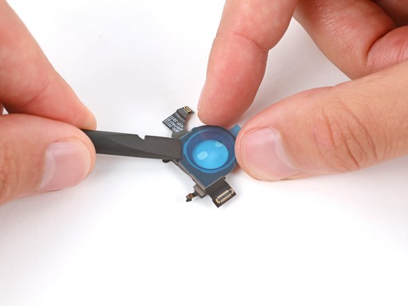
- Remove any adhesive on the underside of the sensor with a pair of tweezers.
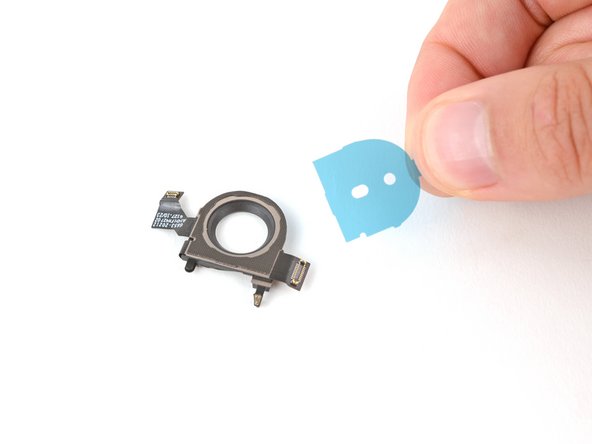
- Remove the larger, clear plastic liner from your replacement autofocus sensor adhesive.
- Carefully apply the adhesive to the bottom of the sensor and press down firmly with a spudger to secure it.
- Peel up the remaining blue liner.
- Be very careful not to touch the camera lenses during this step. If you accidentally do, wipe them with a clean microfiber or lint‑free cloth.
- If your replacement rear cameras have protective caps or liners, remove them.
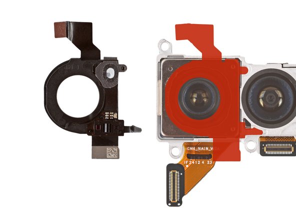
- Before applying the autofocus sensor to your replacement rear cameras, hold the sensor over your replacement cameras and find its proper orientation.
- There are cutouts on the left edge of the middle camera that line up with the short protrusions on the right edge of the sensor.
- Carefully lay the sensor over the rear camera and use your fingers to press it into place, securing it with the adhesive.