Westinghouse Stick Mixer 800W Teardown
ID: 175857
Description: The Westinghouse WHSM02SS 800W Stick Mixer is...
Steps:
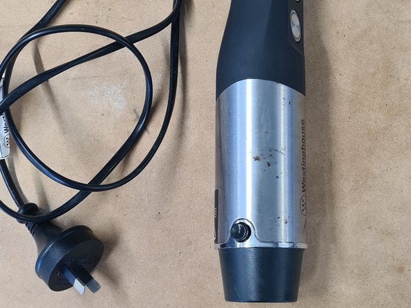
- The Westinghouse Stick Mixer features a multitude of pieces, including:
- Stick Blender
- Puree Attachment
- Whisk Attachment
- Chopper Attachment
- Beaker
- Chopping Bucket
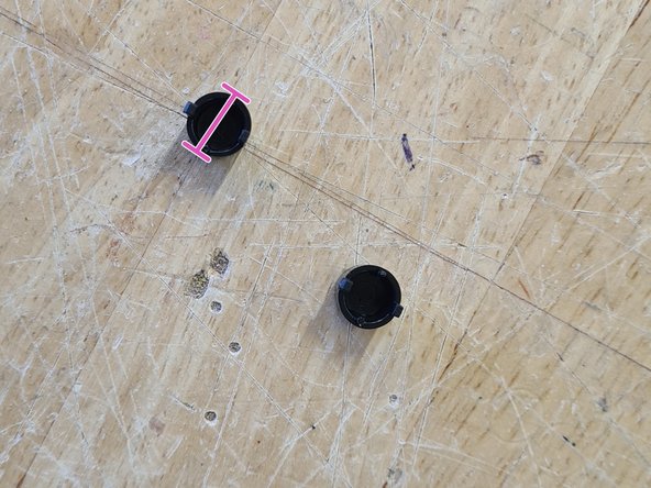
- The device uses 2 buttons to attach different accessories to the base shaft section. These buttons (<1g) are press fit in, and with enough force they can be removed
- Diameter: 9mm
- Upon removing the buttons, the silver trim (<1g) around the base can be slid off
- Diameter: 54mm
- Height: 16mm
- Following this, the metal sleeving (20g) can also be removed. This casing requires some force to take off as the tolerances are very low
- Diameter: 54mm
- Height: 91mm
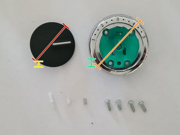
- Pry the top dial face (<1g) off using either a pry tool or a slotted head screwdriver. The dial face is made from a rubberised material
- Diameter: 40mm
- Height: 12mm
- Upon prying, remove the click indicator, shaft, and retention spring. These are situated behind the face, providing tactile feedback to the user when operating the dial
- Unscrew the 4 12mm long exposed button head M2 Phillips screws (<1g), allowing removal of the dial housing (3g)
- Diameter: 53mm
- Height: 20mm
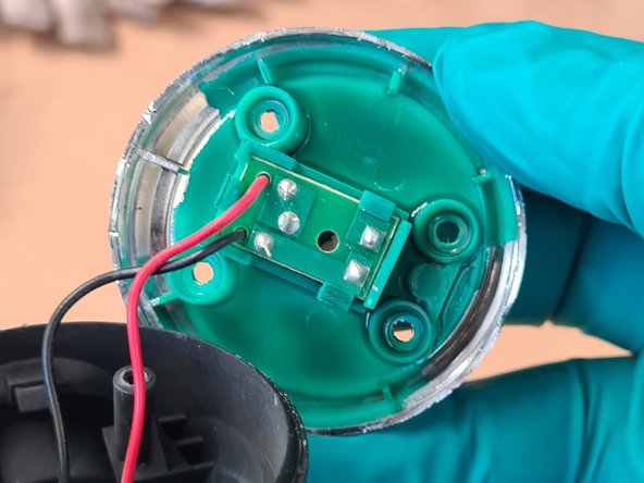
- Behind the housing seats a potentiometer PCB. This can be slid out from its clips. The potentiometer functions as a speed indicator, with the changing resistance corresponding to a different speed setting
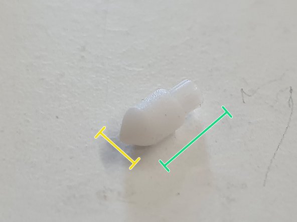
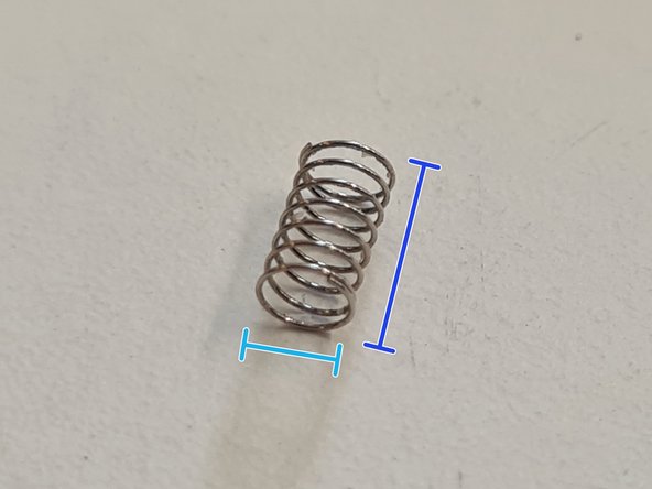
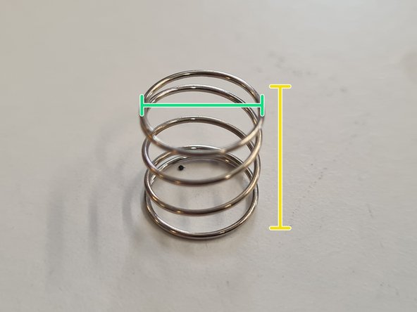
- The dial mechanism is made up of a few different parts, including the click indicator (<1g), shaft (<1g), and retention spring (<1g). The purpose of these parts are to provide tactile feedback for users when adjusting the speed.
- Diameter: 3mm
- Length: 15mm
- Diameter: 3mm
- Length: 7mm
- Diameter: 2mm
- Length: 5mm
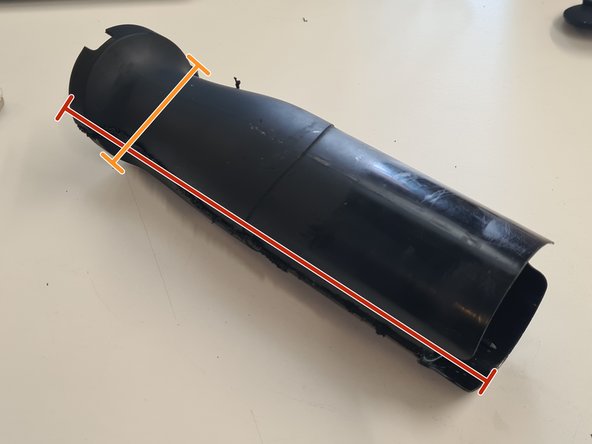
- The main plastic body (95g) can now be removed. Ideally, this would be heated up to melt the glue holding in place the accessory attachment point to the frame, however in this case a plaster saw was used along the part lines to separate the shell
- Height:183mm
- Diameter: 54mm
- After the shell is cut, we can access the motor, main PCB, and accessory attachment point. These parts can be pulled apart with some force
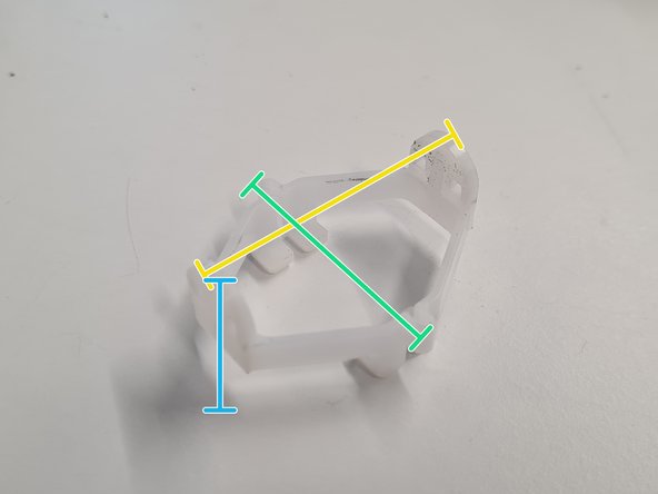
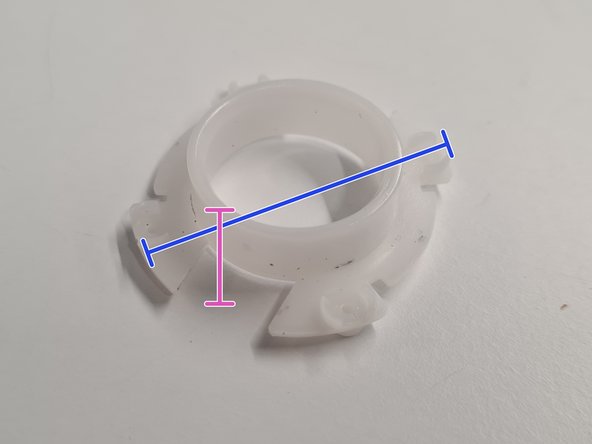
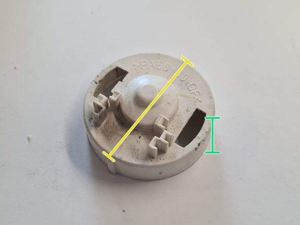
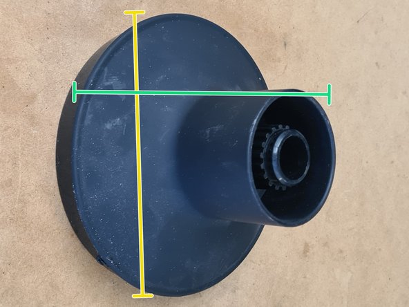
- The accessory attachment point is made from 3 parts: the outer shell (13g), a plastic spring (<1g), and a plastic bracket (<1g). The attachment point features several fins to aid with the alignment of accessories such as whisks, blades, etc.
- Diameter/Height: 52mm
- Lenght: 43mm
- Width: 39mm
- Height: 22mm
- Diameter: 44mm
- Height: 12mm
- There appears to be provisions to screw the bracket and spring to the shell, however no screws were present within this particular model.
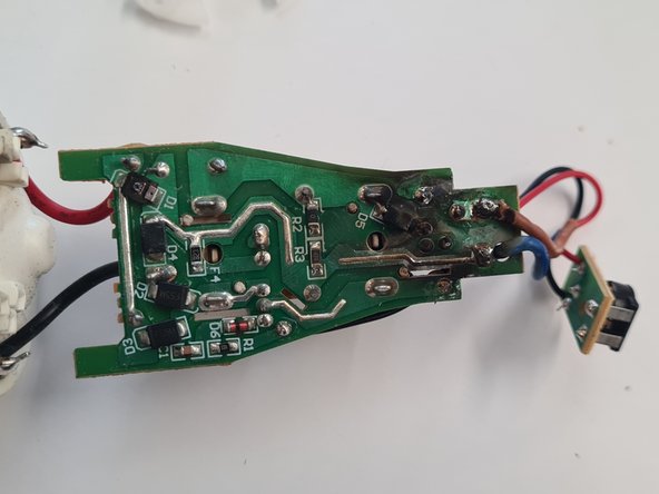
- The PCB (8g) is permanently soldered to the motor. It features 2 momentary switches, controlling the on/off function and 'boost' function. There are also 2 ceramic capacitors, a transistor, a 'Tenta" safety capacitor, and 2 LED indicators
- Length: 70mm
- Width: 34mm
- On the back side of the PCB features multiple diodes and resistors. There are signs of clear damage around the 'D5' diode leading from the mains 240VAC input. This may have been caused due to heat, leading to catastrophic failure of the device
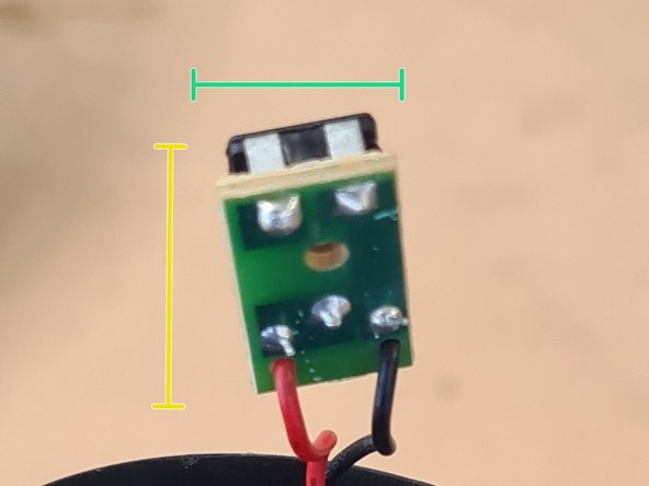
- The potentiometer daughterboard (<1g) is also soldered onto the main PCB
- Length: 20mm
- Width: 11mm
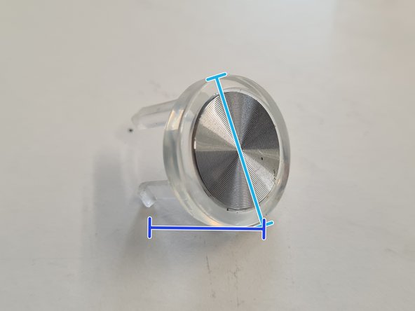
- Attached to the PCB are the momentary buttons (2g) which control on/off and boost functions. These buttons are texturized for ease of locating, and feature passthrough for LED indication. They feature a spring (<1g) to return to their 'off' state
- Diameter: 9mm
- Height: 12mm
- Diameter: 19mm
- Height: 15mm
- The mains power cable (7g) is also routed through to the PCB. It solders onto the top of the board, separated from the other componentry to protect from the high AC voltage
- Length: 1070mm
- Diameter: 40mm
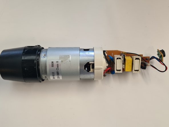
- The motor (500g) is labelled DN8112, a class 180, 800W motor, rated for 220-240VDC. The motor is held in place with a plastic bracket (2g) and has a shaft permanently mounted for attachments.
- Height: 130mm
- Diameter: 50mm
- Height: 11mm
- Diameter: 45mm
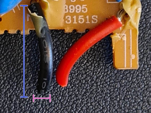
- Looking through the vent holes, the copper windings are visible. The carbon brushes can be accessed from the sides of the motor for possible replacement/refurbisment. They are connected to twin 14AWG wires (<1g)
- Length: 20mm
- Diameter: 2mm
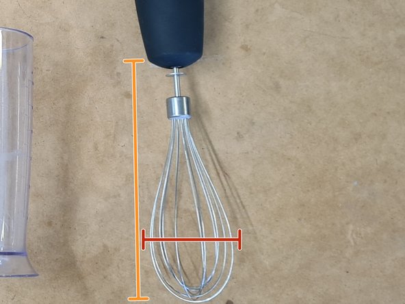
- In addition to the mixer, there are several accessories that come with it, including the whisk attachment. This piece can be broken down into 2 distinct pieces, the whisk head (80g) and gearbox attachment (102g)
- Diameter: 51mm
- Height: 72
- Diameter: 62mm
- Height: 135mm
- The gearbox attachment is geared for speed reduction, increasing rotational torque to allow for better whisking action.
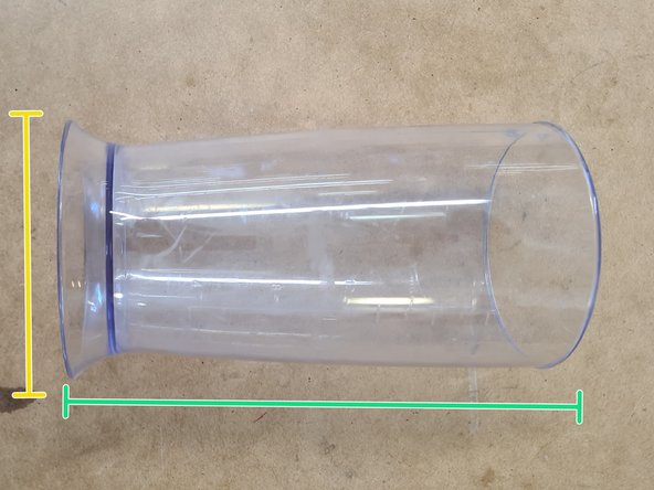
- The puree arm (147g) is a long shaft-driven blade intended to crush and pulp. It is intended to be used with the beaker (110g), with both pieces fitting together. The arm is made from stainless steel, as it will be submerged within food when in use. The clear acrylic beaker aids with visualising food and cleaning
- Diameter: 60mm
- Height: 197mm
- Diameter: 90mm
- Height: 172mm
- The chopper is an enclosed unit designed to dice and mince food. It is made up from the chopper blade (12g), chopper lid (105g) and chopper basket (160g). Likewise to the beaker, the chopper too is made from clear acrylic to aid with monitoring food and cleaning. The blades are made from stainless steel, and are serrated to assist in cutting
- Length: 95mm
- Width: 40mm
- Height: 85mm
- Diameter: 118mm
- Height: 80mm
- Diameter: 125mm
- Height: 115mm
- The device has been fully dissassembled!
- This teardown was irreversible, as cutting was involved in opening the main body. This could be circumvented in the future with heat and isopropyl alcohol to breakdown the adhesives.
- For the most part, this device was not designed with repairability in mind. To fix most parts, complete replacements are required.