Pentax ME Super Main PCB Replacement
ID: 176060
Description:
Steps:
- Wrap a piece of masking tape around your thumb, sticky side out.
- Turn the wind lever cap clockwise to remove (it is reverse threaded).
- Remove the wind lever lock ring (it is also reverse threaded).
- Remove the brass spring washer.
- A pair of fine tipped pliers or nippers can be used in place of a spanner wrench. Be careful!
- Place a tool in the fork of the rewind spindle.
- Unscrew the rewind lever.
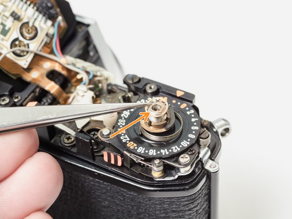
- Remove the lock ring with a spanner.
- Lift off the ISO/Exposure Compensation dial.
- Ensure that the ISO dial couples with the tab on the resistor.
- Turn the Exposure Compensation to 1/4x then back to 4x while gently pushing down. This will help the dial engage with the detent mechanism properly.
- Remove two 3.3 mm #00 screws.
- Remove one 3.2 mm #00 screw.
- Remove one 2.6 mm #00 screw.
- Remove two 4.3 mm #00 screws.
- Lift off the top cover. The silver trim piece is loose and may fall away.
- Remove loose washer.
- The shutter pin is loose. Make sure it is in place before installing the top cover.
- The mode dial pin must be properly coupled with the mechanisms in the camera for it to work.
- Set the mode dial to 'M'. Place the top cover on the camera. Move the mode dial to 'B' then back to 'M' while gently pushing down.
- The mode dial should click into place and work properly.
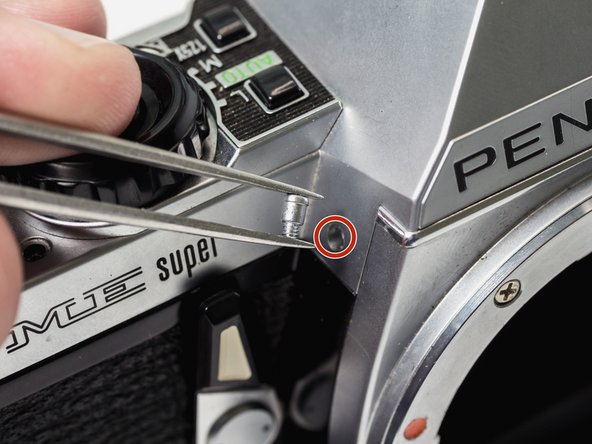
- Use a spanner or tweezers to remove remove self-timer screw. It is reverse threaded.
- Remove self-timer lever.
- Remove black spacer.
- Remove spring washer.
- Remove two 3.0 mm #00 screws.
- Remove one 2.1 mm #00 screw.
- Remove loose plastic cover for motor drive pins.
- Unsolder two yellow wires.
- Remove one 3.0 mm #00 screw.
- Remove one 5.9 mm flat head screw.
- Lift off ISO resistor.
- Unsolder one red wire (positive battery).
- Unsolder one pink wire.
- Unsolder one purple wire.
- Unsolder the red and blue wires (positive battery). They may share a pad.
- Unsolder one gray wire.
- Unsolder one white wire.
- Unsolder one brown wire.
- Unsolder one metal contact.
- Unsolder one pink wire.
- The wiring in this area varies with ME Supers from different production years. You may need to document the wiring for your own camera separately.
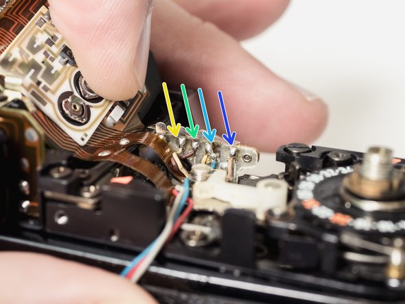
- Unsolder one green wire.
- Unsolder one blue wire.
- Unsolder one red wire.
- On some cameras the wiring order may be green/red/blue.
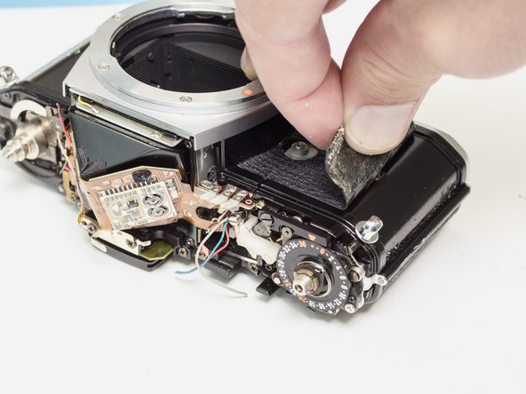
- Apply isopropyl alcohol to soften the leatherette adhesive.
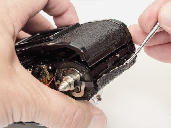
- Use a dull scraper to left the edge of the covering.
- Peel the leatherette away and remove it from both sides of the camera front.
- Installation Notes: Use contact cement to reapply the leatherette. This should be the very last step in reassembly, after the camera is tested and functionality is confirmed.
- Remove two 3.4 mm #00 screws.
- Remove flex PCB retainer.
- Remove shim washers. Note the location (left or right) and install in the same positions during reassembly.
- Remove four 4.0 mm #0 screws.
- Temporarily replace the advance lever and cock the shutter.
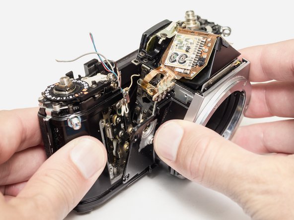
- Gently lift the front block away from the camera body. Move slowly and look for wire snags.
- Cock the shutter on the camera body. The mirror box should be uncharged before installation.
- Twist the three motor drive wires together to easily insert them through the bottom of the camera.
- Carefully track wire routing during installation. Make sure nothing is getting pinched and that all wires are accessible for resoldering.
- Once the front block is in place, check the mechanical speeds of the shutter before completing the reassembly. The mirror and shutter should function normally.
- Remove one 3.4 mm #00 screw.
- Gently work the LED strip out of the slot in the mirror box until it hangs free.
- The old dust/light seal foam will probably fall apart when the LEDs are removed. It should be replaced with new foam strips during reassembly (1.5 mm open cell foam with adhesive backing).
- Installation Notes: The LEDs will need to be realigned with the text in the viewfinder. Use the play in the screw to properly position them.
- Unsolder one gray wire (flash sync).
- Remove two 3.4 mm #00 screws.
- Slide eye piece out of its metal frame. It is still attached to the main flex PCB.
- The PCB is attached to the prism with double sided tape.
- Use isopropyl alcohol to loosen the adhesive and gently work the PCB free from the prism. Work slowly.
- Pull the PCB out of the slot connector at the base of the mirror box.