AT-LP120-USB Spotlight Replacement
ID: 176319
Description:
Steps:
- Disconnect any cables from the rear of the turntable and move it to a clear surface.
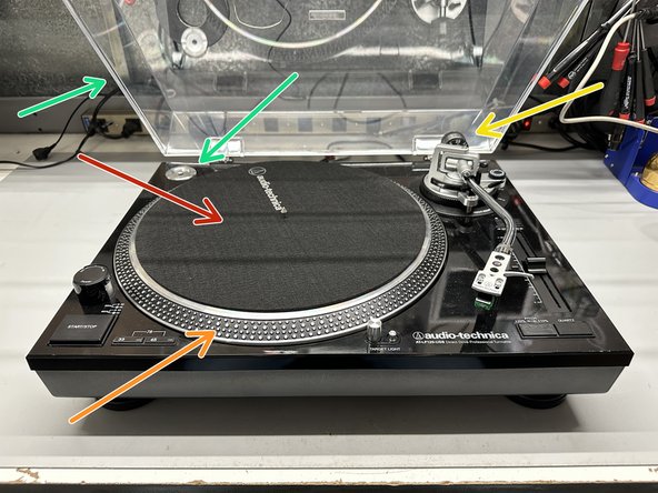
- With the turntable facing you, open the dust cover and remove the following:
- Black felt mat
- Platter
- Counterweight
- 45 Adapter & Dust Cover
- Any other loose accessories that may be on the surface of the turntable should be removed.
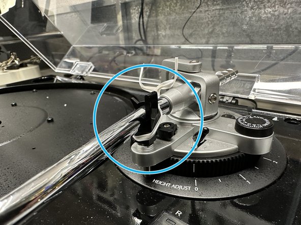
- Tie down the tone arm.
- Before flipping the turntable upside-down, get a large soft object (ex. pillow, blanket, etc...) to minimize the possibility of damage.
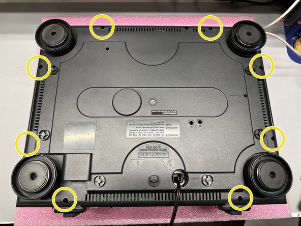
- Using a #PH1 Screwdriver, remove the 8 screws marked
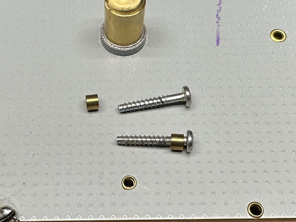
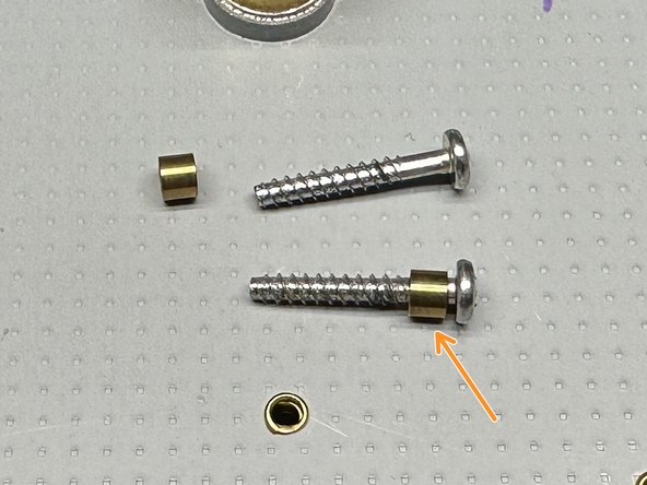
- When removing the 8 screws, there will be 8 brass bushings that are to be placed back on the screws before reassembly.
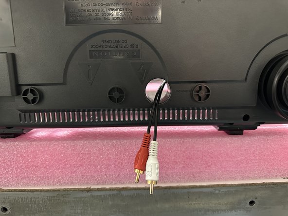
- When removing the bottom cover, you will likely need to tilt the cover towards the back (side with the RCA cables) in order to get the cover to move around the ports.
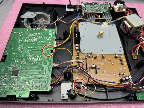
- With the bottom panel removed, locate the two yellow leads from the spotlight, and their connection points.
- There may be adhesive covering the connections, you will need to remove the adhesive.
- This step involves using a soldering iron. If you're not comfortable handling one, it's recommended to seek assistance from a qualified technician.
- With a soldering iron, carefully heat the connection points where the wires are attached. Once the solder melts, gently remove the wires.
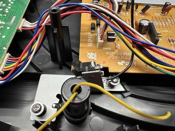
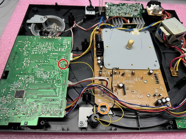
- The shorter lead connects to the top pin of the switch near the spotlight, whereas the longer lead gets connected to the 12V pad on the main PCB.
- Short Lead
- Long Lead
- Using a #PH1 screwdriver, remove the screw and accompanying hardware from the spotlight housing.
- This is the only thing holding the spotlight in place, once the screw is removed the metal housing and spotlight can be pulled through the top of the turntable.
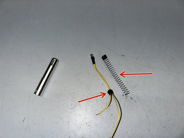
- With the metal housing and spotlight removed, pull off the spring and rubber grommet from the old spotlight and attach them to your new spotlight.
- Pull the yellow leads through.
- Slide the metal housing in place and reattach the screw and bushing.
- This step involves using a soldering iron. If you're not comfortable handling one, it's recommended to seek assistance from a qualified technician.
- Solder the longer yellow lead to the 12V pad of the main PCB.
- Solder the shorter yellow lead to the top pin of the switch near the spotlight.
- Pull the RCA cables through the bottom cover.
- When attaching the bottom cover, you will likely need to tilt the cover towards the back (side with the RCA cables) in order to get the cover to move over the ports.
- Fasten the brass bushings onto all 8 screws
- Using a #PH1 Screwdriver, secure the bottom panel with the 8 screws.