Portable Power Station Display Removal
ID: 177908
Description: Prerequisite‑only guide for removing the...
Steps:
- Let your Portable Power Station's battery drain below 25% before starting this repair. A charged lithium‑ion battery may catch fire if damaged.
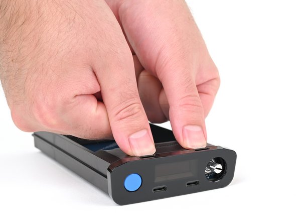
- Hold down the blue action button for five seconds to shut down your power station.
- Collapse the kickstand.
- Throughout this repair, keep track of each screw and make sure it goes back exactly where it came from.
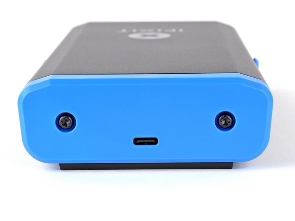
- Use a T10 Torx screwdriver to remove the two 8 mm‑long screws securing the rear cover.
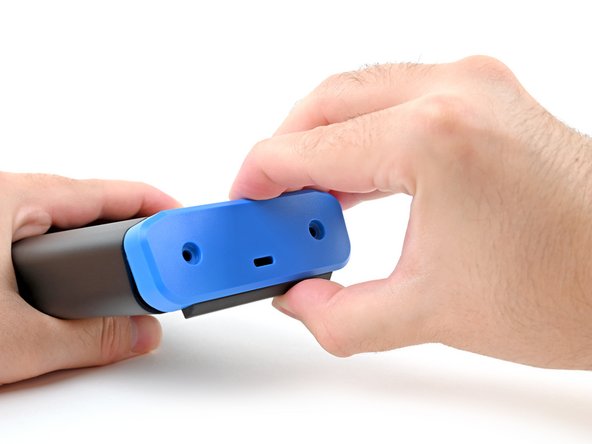
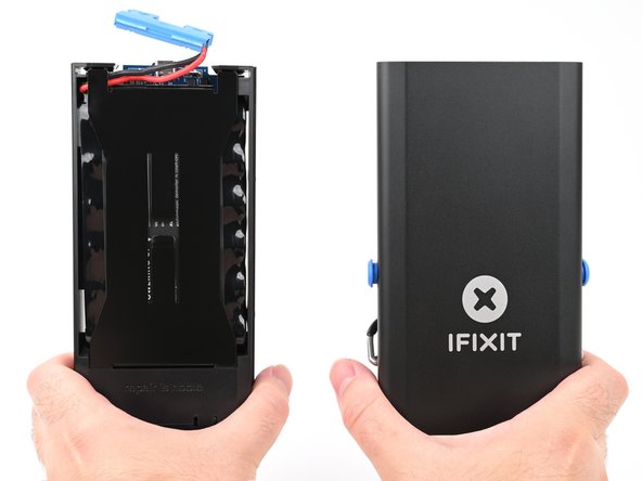
- Grab the rear cover and pull the bottom edge towards you.
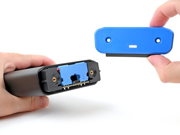
- Remove the rear cover.
- Don't try to remove the enclosure while the battery is still connected, or you'll damage the battery connector.
- During reassembly, hook in the top edge of the rear cover first, then press the bottom edge into place.
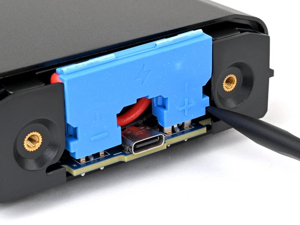
- To avoid an electrical shock, don't use metal tools to disconnect the battery.
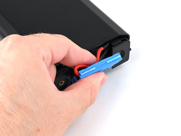
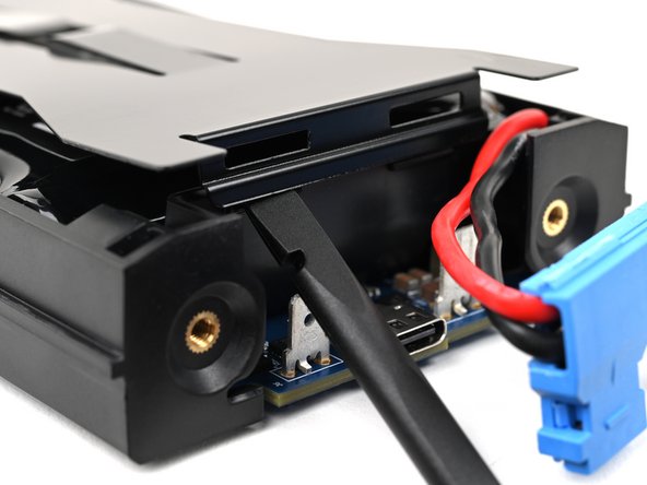
- Insert the flat end of a spudger into one of the slots on either side of the battery connector. They're shaped just for this!
- Use the spudger to begin prying up the connector.
- If it's your first time disconnecting the battery, this may take some force.
- Just when the connector starts to move, continue to the next step.
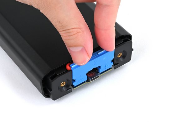
- Repeat the process and pry up on alternating sides of the battery connector to "walk" it off of the two plugs, enough that you can easily grip it with your fingers.
- You may have to reposition your spudger to fully release the battery connector. Be careful not to damage the board if you pry against it.
- Don't try to force the connector off or you might hurt yourself on the metal edges of the enclosure. If the connector doesn't come off easily, continue prying up with your spudger until the connector is loose enough to easily disconnect.
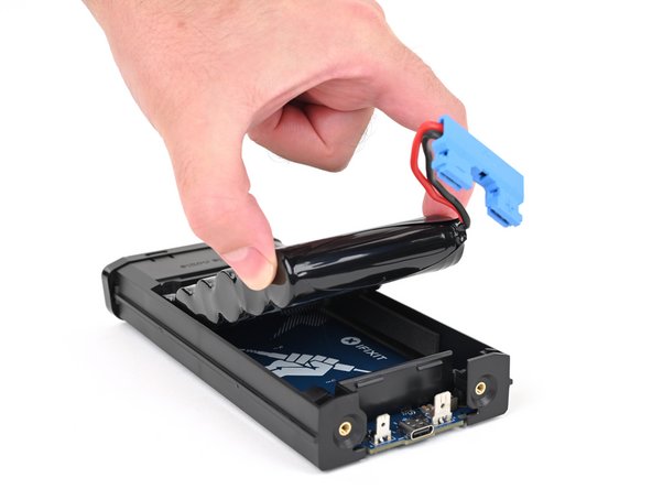
- Grasp the battery connector by its edges and pull straight up to disconnect it.
- During reassembly, follow these steps to reconnect the battery:
- Tuck the wires behind the connector, so the side of the connector with positive (+) and negative (-) markings is facing outward.
- Make sure the wires aren't pinched by the enclosure.
- Align the connector over its two metal plugs so the negative (-) side is on the left of the USB‑C port and the positive (+) side is on the right.
- Slide the connector onto its plugs and push down firmly until it's fully seated.
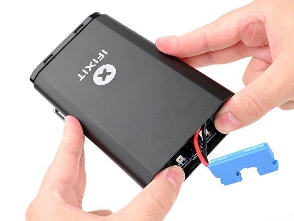
- Place your fingers on the rear cover screw holes and push the chassis slightly out of the enclosure.
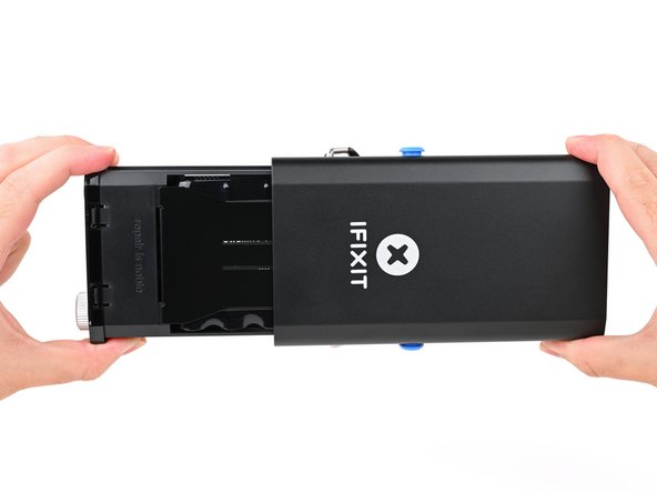
- Slide the chassis fully out of the enclosure, making sure the battery connector doesn't get snagged.
- During reassembly:
- Make sure the battery is disconnected before sliding the chassis into the enclosure. Otherwise, you'll damage the battery connector.
- Insert the battery connector side of the chassis into the end of the enclosure closest to the kickstand and slide it into place.
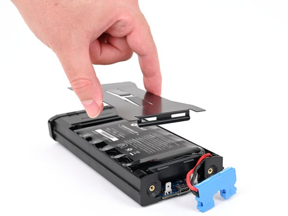
- Use the flat end of a spudger or a clean fingernail to pry up the edge of the metal battery cover closest to the battery connector.
- The battery cover locks the battery in place. Once removed, the battery becomes free to fall out of the power station.
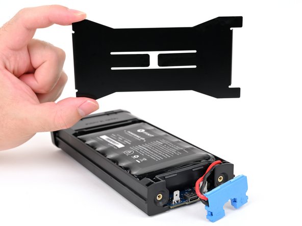
- Remove the metal battery cover.
- During reassembly:
- Hook the short edge of the cover without cutouts into place at the front, near the display.
- Firmly press down on the opposite edge of the cover until it clips into place.
- Make sure the battery cover doesn't pinch the battery cables—they should be routed under the cover and angled inward.
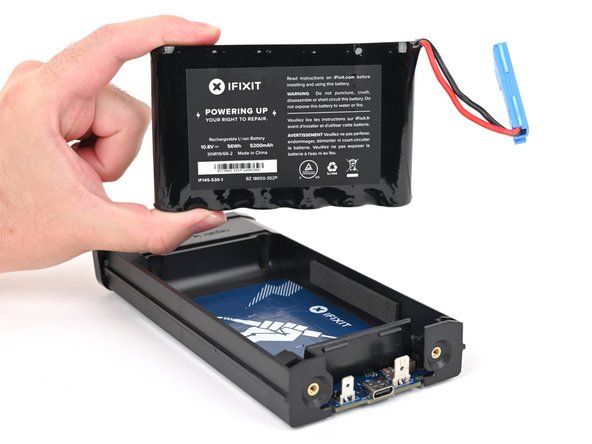
- Remove the battery.
- During reassembly, don't reconnect the battery until after the enclosure is installed, or you'll damage the battery connector when everything goes back together.
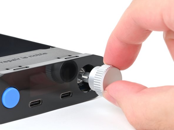
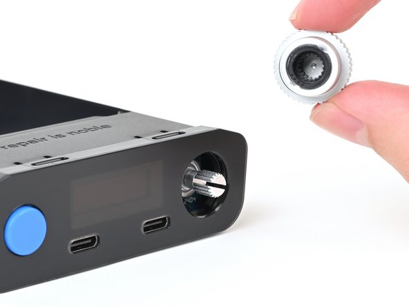
- Pull the silver selector knob directly away from the front panel to remove it.
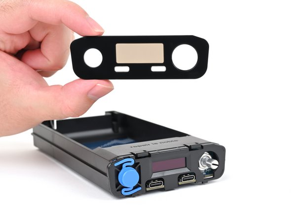
- Use your fingers to depress the two locking tabs holding the front panel in place.
- Press on the clips themselves (just behind the front panel) and not through the cutouts on the top edge of the front panel.
- While pressing the tabs down, push the front panel away from the chassis and remove it.
- During reassembly:
- Hook in the bottom edge of the front panel first, then push the top edge until it clicks into place.
- Make sure the two USB-C ports slide into their cutouts in the front panel and aren't trapped underneath.
- Flip your power station over.
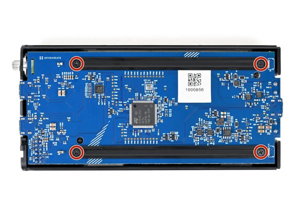
- Use a Phillips screwdriver to remove the four 6 mm‑long screws securing the two main board supports.
- Hold the supports in place while removing the final screws. Otherwise, the support may swing onto the board and damage the small, surface‑mounted components.
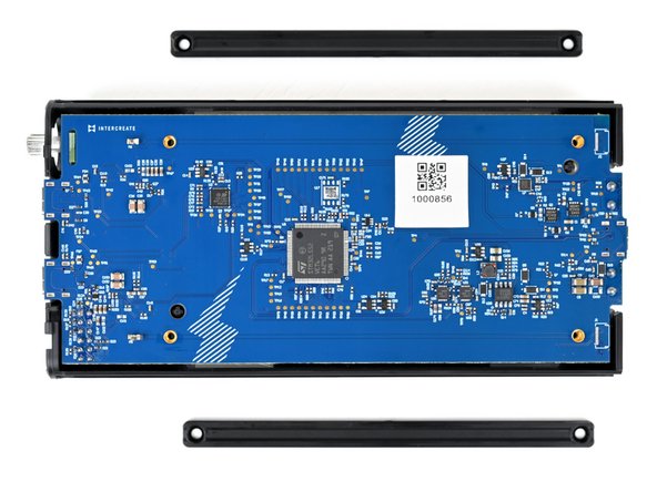
- Remove the main board supports.
- During reassembly, make sure the beveled sides of the main board support screw holes face up.
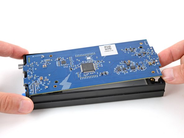
- Use your finger to gently lift the main board by the USB‑C port, enough that you can grip the board's edges.
- With one hand, firmly secure the chassis.
- With your free hand, grip the main board near the center.
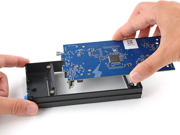
- Lift the board straight up and pull it away from the display to remove it, threading the selector knob through its cutout.
- Long pins on the main board plug into the UI board and hold it in place.
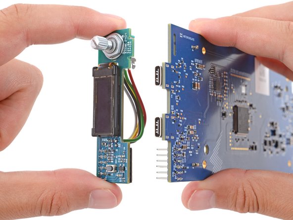
- With one hand, hold on to the main board.
- Don't press the board down against your work surface, or you may damage the surface‑mounted components on the board.
- With your free hand, grip the UI board by its edges and firmly pull it straight away from the main board to disconnect it.
- Make sure the boards stay perpendicular to each other or the pins might get damaged.
- During reassembly:
- When pushing the UI board back into place, make sure the side opposite the sockets goes into its cutout on the main board. Otherwise, it will prevent the UI board from fully seating.
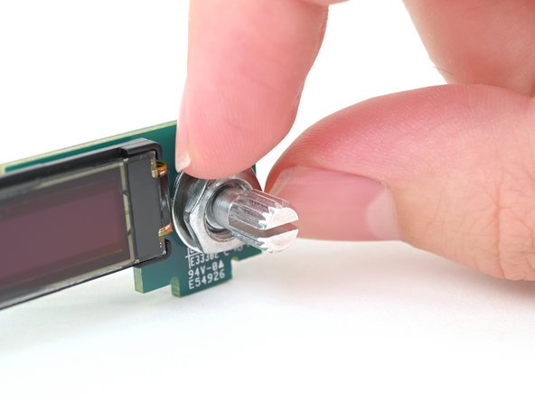
- Use your fingers, small pliers, or a 10 mm wrench to loosen the thin nut securing the selector knob.
- If you're using pliers or a wrench, be careful not to scrape the display or the board.
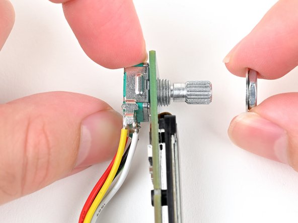
- Pull the nut and its washer off the front of the knob and remove them.
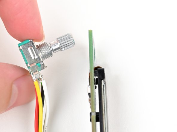
- Pull the knob out of its cutout to free it from the UI board.
- The selector knob assembly is still attached to the UI board by its cables.
- Hold the knob and its cables out of the way as necessary while working on the UI board.
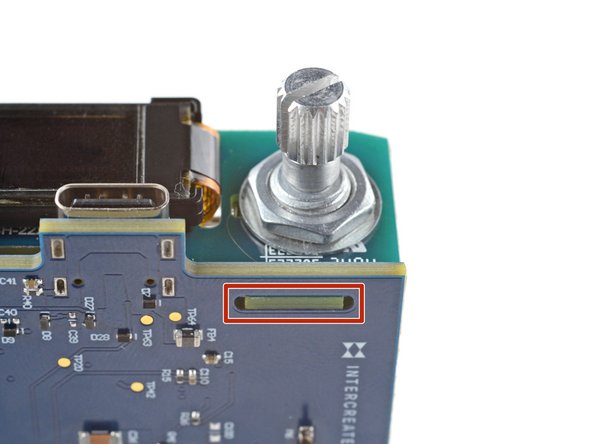
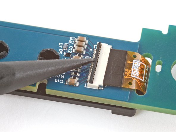
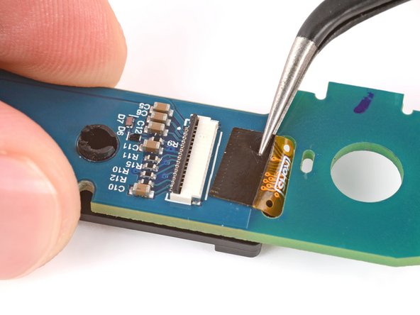
- Be very careful not to damage any of the small, surface‑mounted components near the connector.
- Use the point of a spudger to flip up the locking flap on the display cable ZIF connector.
- Use angled tweezers to grip the display cable and gently pull it straight out of the socket.
- During reassembly, use your finger to carefully slide the cable back into the socket.
- Be careful not to damage any of the small, surface‑mounted components on the board.
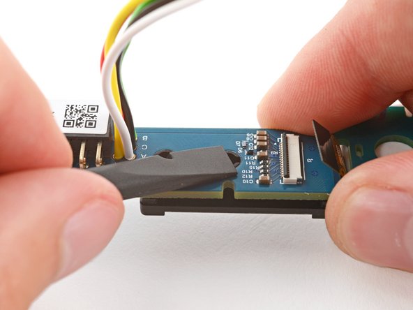
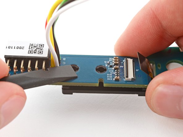
- Hold the UI board slightly above your work surface and use the flat side of a spudger to firmly push the two display pegs through their cutouts on the board.
- This is tricky and might require multiple attempts. Alternatively, you can use blunt‑nose tweezers to squeeze the pegs together to release them.
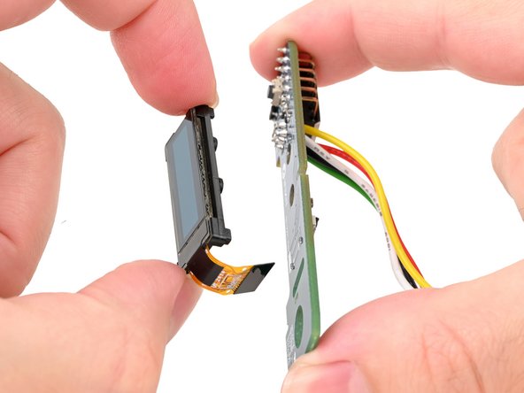
- During reassembly, push the pegs into their holes on the UI board until they click into place.
- Remove the display.
- During reassembly, make sure to thread the display cable through its cutout on the UI board.