Basic LED Flashlight DIY Soldering Kit Assembly
ID: 178085
Description: Follow this guide to build a flashlight using...
Steps:
- If you're working indoors, place your fume extractor next to your project. Set up your tools in a well-lit area, away from anything flammable:
- A pair of safety glasses (solder spatter will damage regular glasses)
- A soldering iron and solder (leaded or lead-free)
- Board holder, or "helping hands" tool
- A tip cleaning tool (damp cellulose sponge or brass wool)
- A pair of flush cutters
- Solder wick (aka desoldering braid) and/or a desoldering pump, in case you make a mistake.
- (Optional) A silicone work mat to prevent damage to your work surface.
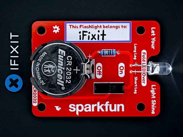
- Your flashlight kit contains the following parts:
- Circuit board
- 10 Ω (brown-black-black-gold-brown) resistor
- CR2032 battery connector and foam block
- Don't throw away the foam block—you'll need it later on.
- Toggle switch
- White LED
- CR2032 battery
- Use your fingers to carefully remove the two protective covers from the resistor leads. Avoid bending the resistor leads during removal.
- Hold the resistor body with one finger and bend the leads over the edges of that finger 90‑degrees into a U‑shape.
- If this doesn't work, use tweezers to bend the leads about 1 mm from the resistor body.
- Hold the circuit board so the front (the side labeled "Let Your Light Shine" at the top) is facing you.
- The resistor is symmetrical and can be inserted in any orientation.
- Insert the resistor leads through their holes on the front of the circuit board.
- Hold the resistor flush against the front of the circuit board.
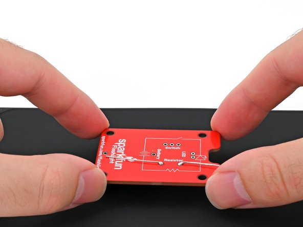
- Flip the board over.
- Bend the resistor leads until they're parallel to the circuit board. This will keep the resistor still while you solder it to the board.
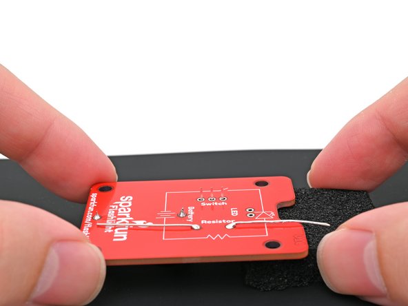
- Use your helping hands to secure the board so the leads are facing up.
- Put on your safety glasses.
- Turn on your soldering iron. If your soldering iron has temperature control:
- Set it to 300 °C (~570 °F) if you're using leaded solder
- Set it to 375 °C (~700 °F) if you're using lead-free solder
- Clean the tip of your soldering iron. If you're using a cellulose sponge, wet the sponge with distilled water until damp and quickly wipe the tip across it. If you're using brass wool, stab the tip into the wire a few times.
- Melt a small glob of solder onto the tip of the iron. This is called "tinning the tip" and will help with heat transfer.
- You'll likely see some wispy smoke as you melt solder. This is mostly the rosin-core flux that's built into the solder wire. Flux helps molten solder flow, but gets vaporized over time.
- If this is your first time using a soldering iron, repeat the cleaning and melting procedure a few times to get a feel for how molten solder handles and how much solder the tip can hold. Clean your tip before continuing.
- In this step, you're going to heat the solder pad and the resistor's lead so that they'll readily melt the solder wire.
- Press the tip against the circuit board's solder pad and the resistor's lead for a few seconds to heat them both. Angle the tip so it has maximum contact with the pad and lead.
- If you heat the circuit board continuously for more than 10 seconds, the excessive heat may damage the solder pad or resistor.
- Feed the solder wire into the heated area until there's a concave pool ("mini volcano") of solder surrounding the lead.
- Don't feed the solder directly onto the tip as it won't flow properly into the pad and lead, causing a weak connection.
- The volcano should form within a few seconds. If the solder doesn't adhere to the pad, apply flux to the pad or increase the temperature.
- Remove the solder wire first, then remove the soldering iron from the pad.
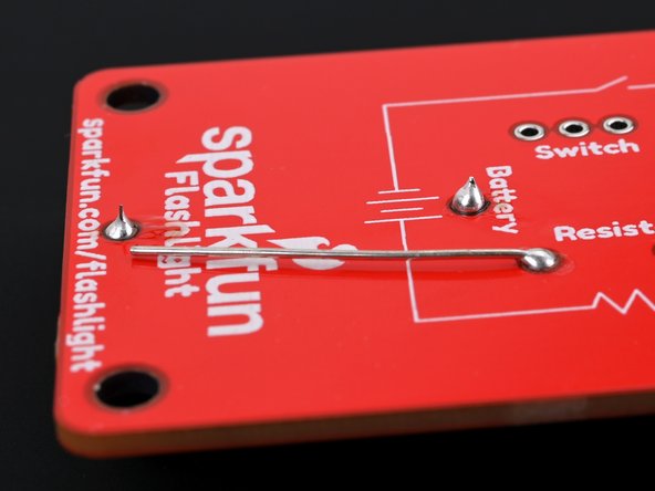
- Repeat this process for the second resistor lead.
- Congratulations—you've soldered the resistor to the board!
- If the solder joint doesn't surround the entire lead, reheat the joint and add more solder.
- Check if any solder unintentionally bridged with a different joint. If so, carefully use your iron to heat the solder between the joints and separate the bridge. If the bridge doesn't want to separate, desolder it and try again.
- Like any skill, practice makes perfect. If your first solder joint doesn't look picture-perfect, that's OK! It takes a few attempts to get the hang of the movement and timing.
- Remove the battery connector from its foam block.
- Don't throw away the foam block—you'll need it for future steps.
- The battery connector is NOT symmetrical and must be oriented correctly using its outline on the board.
- Place the battery connector on its outline on the front of the circuit board. Make sure the leads go through their holes in the board.
- Hold the battery connector flush against the front of the circuit board.
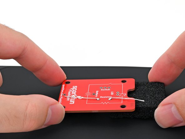
- Flip the board over and set it down so the battery connector is resting on your work mat or surface.
- Place the foam block underneath the top edge of the board (the edge with the notch) to keep it level while you solder.
- Press the soldering iron tip against the circuit board's solder pad and the battery connector's lead for a few seconds to heat them both. Angle the tip so it has maximum contact with the pad and lead.
- Feed the solder wire into the heated area until there's a concave pool ("mini volcano") of solder surrounding the lead.
- Don't feed the solder directly onto the tip as it won't flow properly into the pad and lead, causing a weak connection.
- Remove the solder wire first, then remove the soldering iron from the pad.
- Repeat this process for the other battery connector lead.
- If the second battery connector lead is no longer flush with the board, push it back through while heating the first lead before attempting to solder it in place. If needed, desolder the battery connector and restart this step.
- Double-check that the battery connector is flush with the board and that its solder joints are making a solid connection.
- If the solder joint doesn't surround the entire lead, reheat the joint and add more solder.
- The switch is symmetrical and can be inserted in any orientation.
- Place the switch on its outline on the front of the circuit board. Make sure all three leads go through their holes in the board.
- Hold the switch flush against the front of the circuit board.
- Flip the board over and set it down so the switch is resting on your work mat or surface.
- Place the foam block underneath the board to keep it level while you solder.
- Make sure the switch stays flush with the board and the leads stay level with each other while you're soldering. If it becomes crooked, desolder the leads and try again.
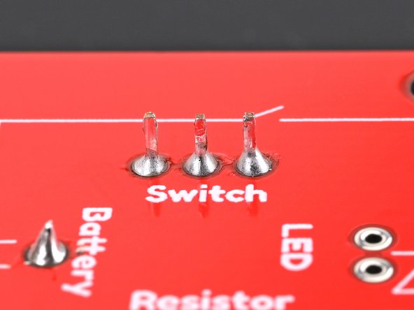
- Solder the three switch leads to the board.
- Double-check that the switch is flush with the board and that its solder joints are making a solid connection.
- Check if any solder unintentionally bridged with a different joint. If so, carefully use your iron to heat the solder between the joints and separate the bridge. If the bridge doesn't want to separate, desolder it and try again.
- The LED is NOT symmetrical and must be oriented correctly.
- Insert the LED leads about halfway into the front of the board, with the longer leg in the hole labeled "Long Leg," and the shorter leg in the hole labeled "Short Leg."
- One edge of the LED's clear epoxy lens is flat instead of round. This flat edge indicates the negative (-) lead.
- Push the LED towards the board (bending the leads) so the lens fits in the notch between the words "Let Your" and "Light Shine" on the top/front of the circuit board.
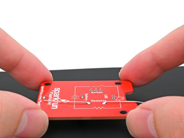
- Flip the board over.
- Bend the LED leads until they are parallel to the circuit board. This will keep the LED still while you solder it to the board.
- Use your helping hands to secure the board so the leads are facing up.
- Solder the two leads of the LED to the board.
- Check if any solder unintentionally bridged with a different joint. If so, carefully use your iron to heat the solder between the joints and separate the bridge. If the bridge doesn't want to separate, desolder it and try again.
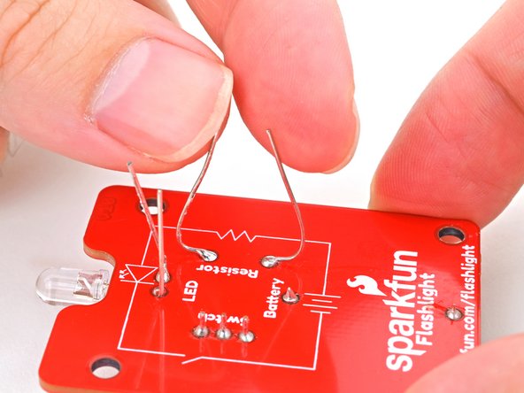
- Bend the resistor and LED leads upwards until they're perpendicular with the board.
- Use your flush cutters to trim all the leads until they're no longer poking up past the solder joint from the back of the board.
- Ensure that none of the wires are long enough to bridge a connection to other leads or poke your hands during use.
- This is a great time to clean up any residue left from the solder. Apply some isopropyl alcohol to the solder joints and wipe with a lint-free cloth to soak up the flux and alcohol residue.
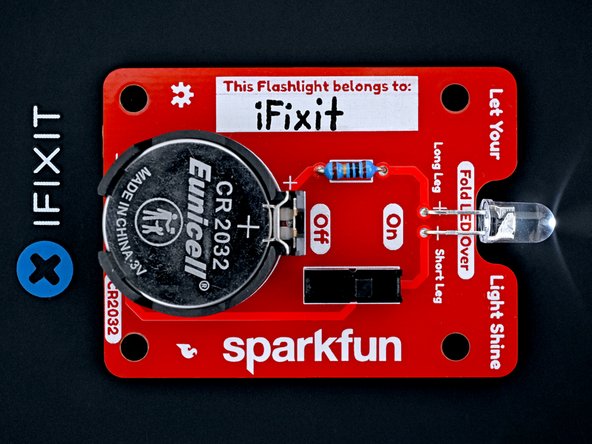
- Set your CR2032 battery in the battery connector with the positive (+) side facing upwards.
- Press down on the battery until it snaps into the connector.
- Congratulations! You now have a functioning flashlight.
- If your switch is in the "off" position, turn it on to power up your flashlight.
- Optionally, write your name in the name tag field.