Samsung Older French Door Refrigerator - Freezer Defrost High Limit Thermostat Test and Replacement
ID: 178089
Description: The high limit thermostat is located on a...
Steps:
- Unplug your refrigerator before you begin your repair.
- If you are testing or repairing the following items, you may also need to shut off and disconnect the water supply:
- Condenser fan motor
- Compressor motor and thermal overload device
- Water supply valve assembly
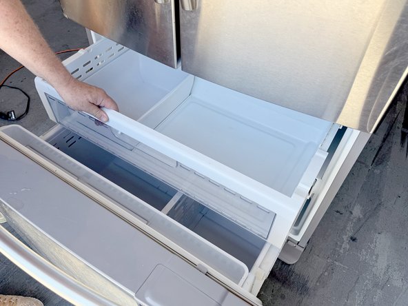
- Open the freezer drawer.
- Pull out the upper freezer drawer.
- Lift the front edge of the drawer.
- Remove the drawer by lifting it up and out of the freezer compartment.
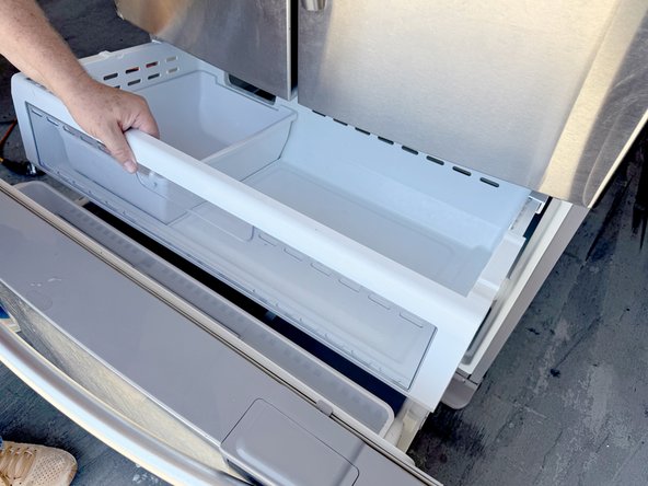
- Unclip the basket hinge retainer by tilting the rear edge up and remove it from the drawer rail.
- Release the small drawer basket and lift it up and out.
- Lift the drawer basket out of the drawer frame and remove it.
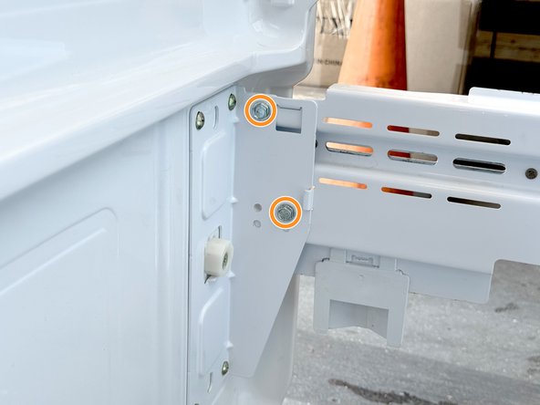
- Use a 3/8" socket wrench, box wrench, or open end wrench to remove the bolts securing the drawer front to the right drawer slide.
- Repeat the process for the left drawer slide.
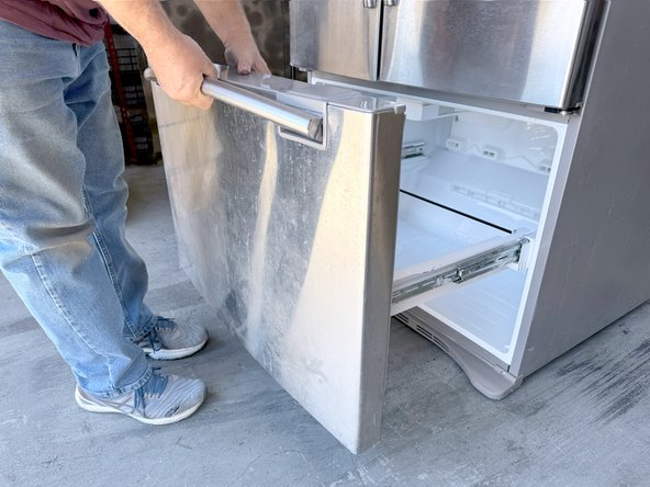
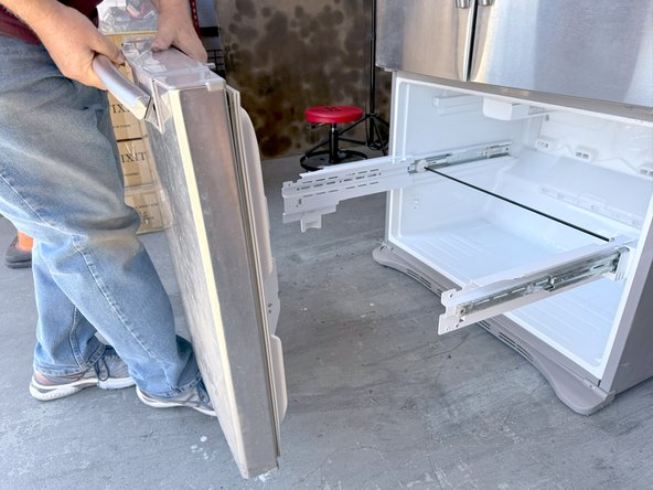
- Lift the drawer front upwards to free it from the drawer slides.
- Remove the drawer front.
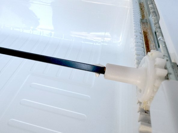
- Rotate the slide connector rod until you can access the retaining pin.
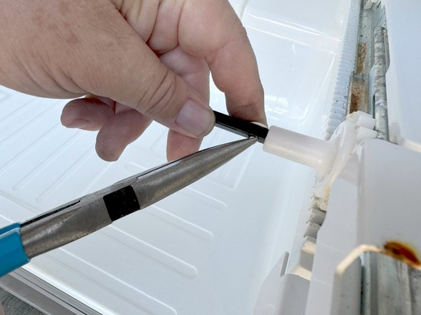
- Use a pair of long nose pliers to squeeze the retaining pin shank to release it.
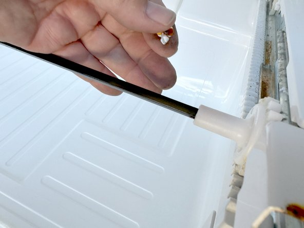
- Pull the retaining pin out of the hole.
- Slide the connecting rod to the right to free the left end of the rod.
- Remove the rod by lifting it upward and sliding it back to the left.
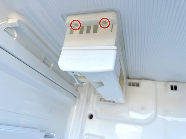
- Use a #2 Phillips driver to remove the retaining screws.
- Two views of the same screws are shown for clarity. There are not four screws.
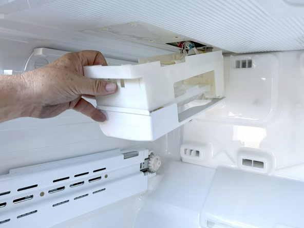
- Pull the icemaker forward parallel to the top of the freezer.
- This will release the icemaker from the freezer top.
- Reposition the icemaker and hold it in one hand to prepare to disconnect it.
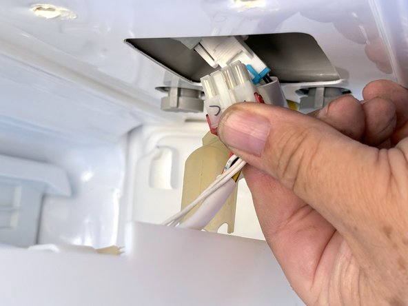
- Grasp the icemaker connector (the one to the front) and squeeze the release tab.
- Pull the connector out from the socket.
- Remove the ice maker.
- This view shows the slots that the mounting studs on the freezer top for reference when reassembling.
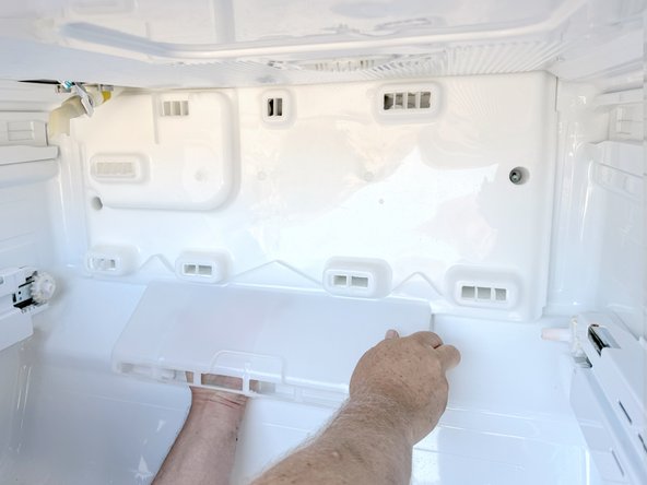
- Use a #2 Phillips driver to remove the screws securing the evaporator cover.
- Lift the evaporator cover from the bottom edge and tilt the edge toward you.
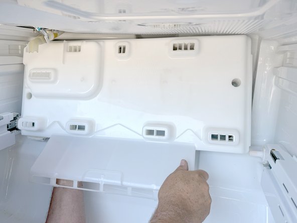
- Reposition the evaporator cover to allow access to the connections to the right rear.
- Don't try to remove the cover yet, as you need to first disconnect the electrical connections to it in the upper right rear of the freezer compartment.
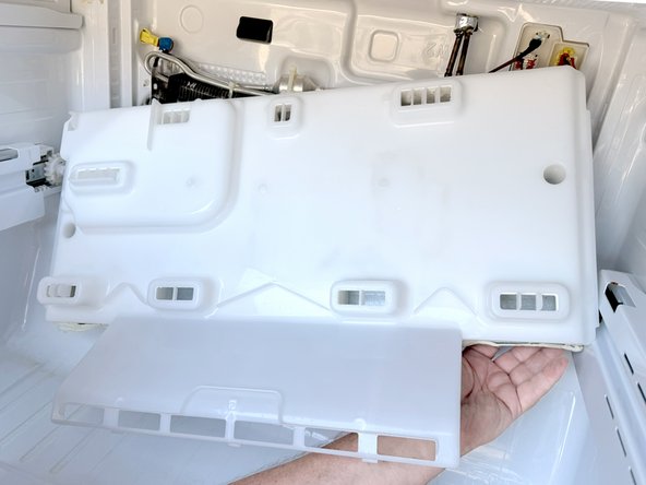
- Disconnect the connectors by squeezing the release tab on the connector and pulling them free of the sockets.
- Support the cover from below so there is not tension on the connections.
- Finish disconnecting the connections while supporting the cover from below.
- Remove the evaporator cover.
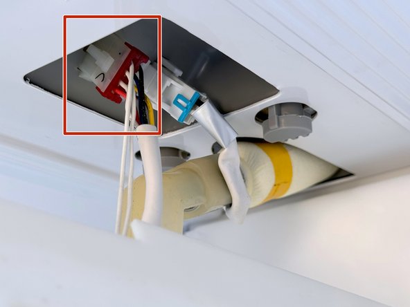
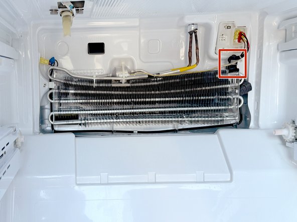
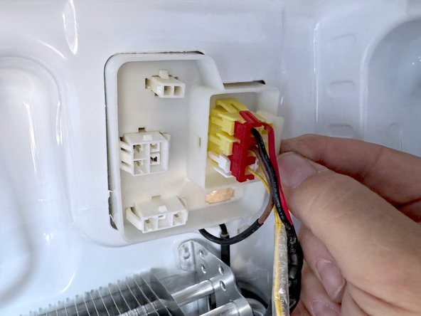
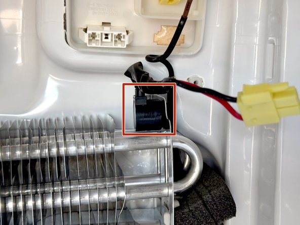
- The high limit thermostat is the device in the red rectangle.
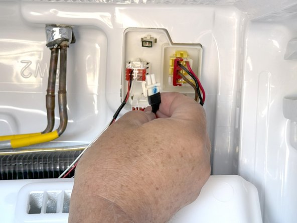
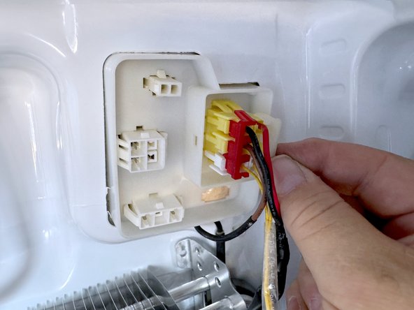
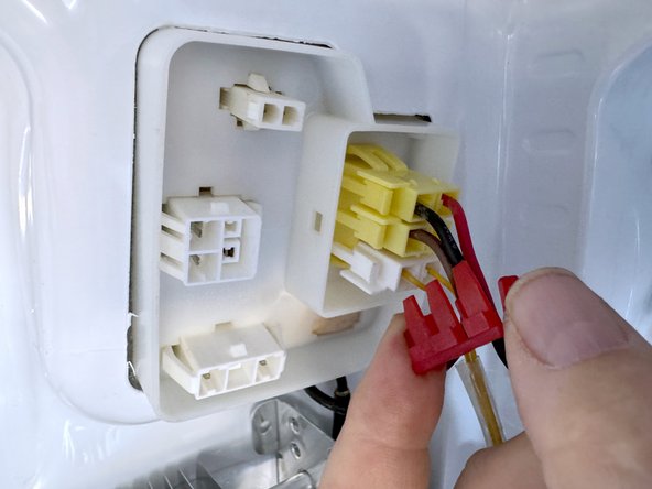
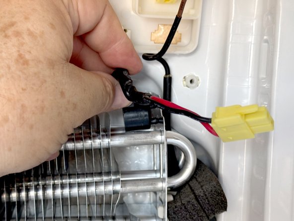
- Remove the light colored connector clip. There are two locking tabs at each end of the clip (top and bottom) that you can lift with a fingernail.
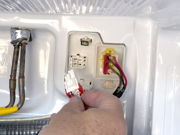
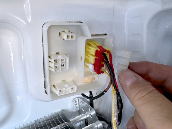
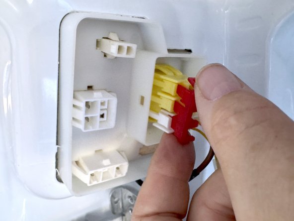
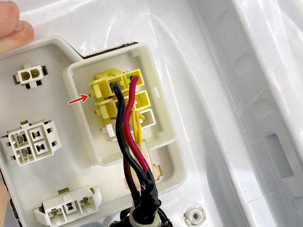
- Remove the red or second connector clip as described in the previous step (it may be another color).
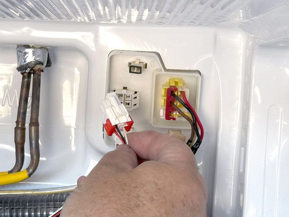
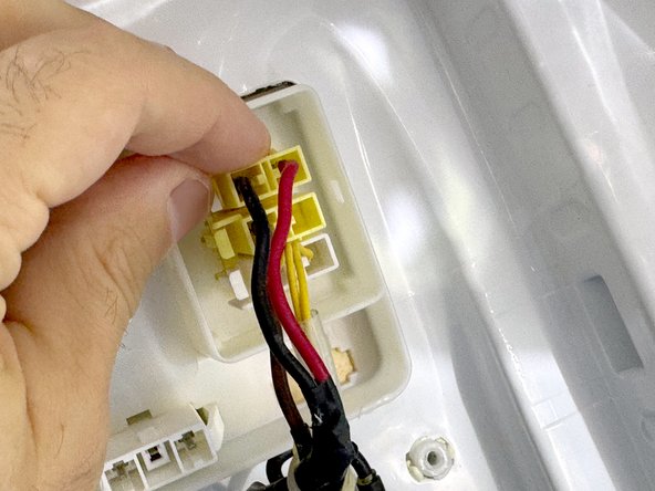
- Push the locking tab in to release the connector.
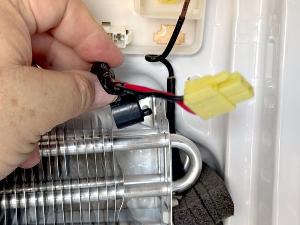
- Use flush cutters to cut the cable tie holding the wiring bundle together.
- Pull the component to the left to remove it from the mounting bracket.
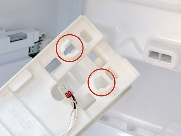
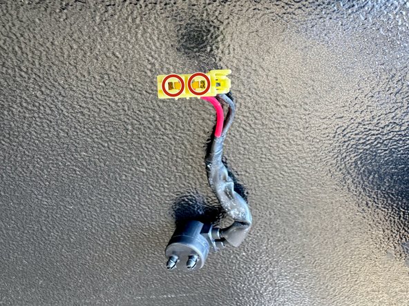
- Red circles showing the connector location for testing.
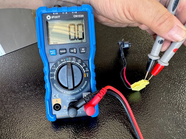
- Test the resistance of the thermostat with a multimeter set to the Ω setting.
- At room temperature the thermostat should have a resistance of use than 1Ω.
- If the thermostat shows a resistance of greater than 1Ω, replace it.