YT-88 Automatic Intelligent Sweeping Robot Full Disassembly
ID: 178406
Description: YT-88 Automatic Intelligent Sweeping Robot...
Steps:
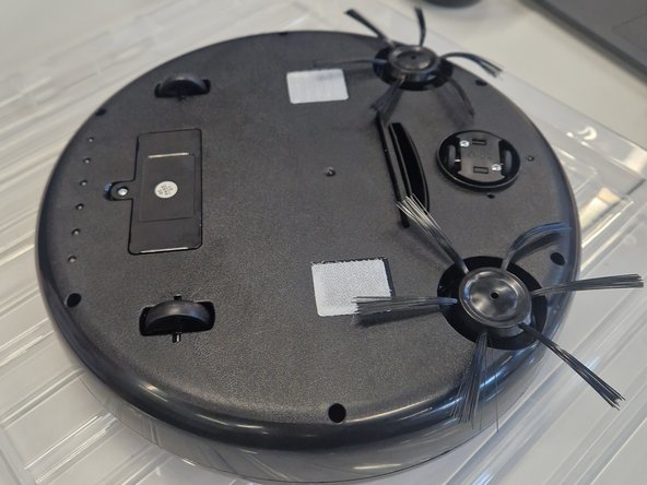
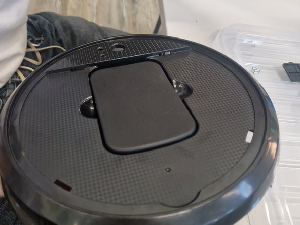
- Turn the robot vacuum upside down to access the screws underneath.
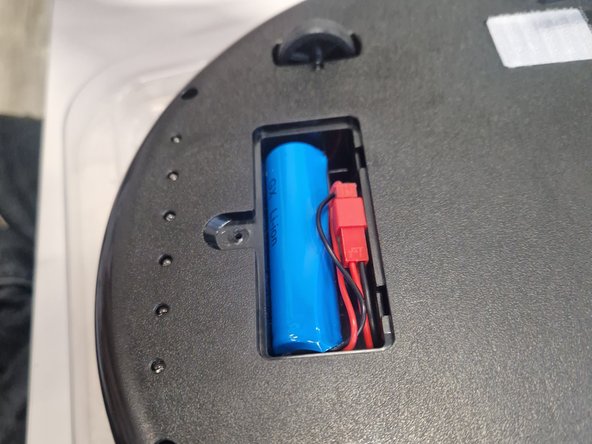
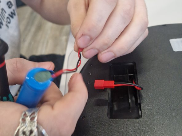
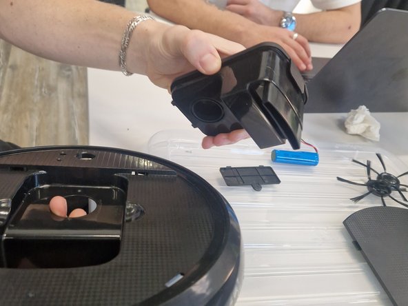
- Using a Phillips 1 screw bit - remove the battery cover and carefully unplug the 18650 rechargeable cell from connector and place it in a safe separate environment along with the battery cover.
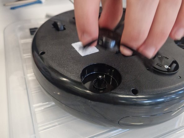
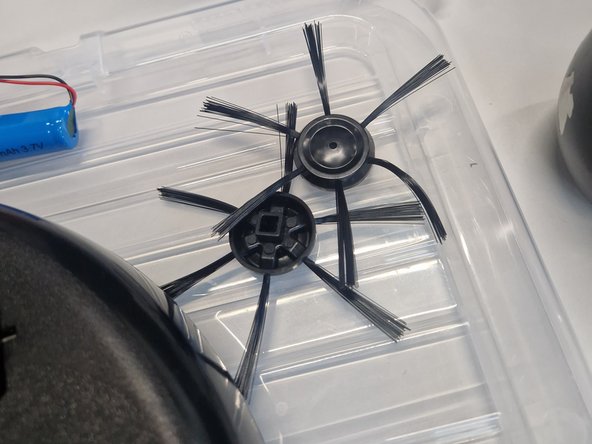
- Using a Phillips #1 screw bit remove the screws from both of the sweepers and using a slight force or using the shaft of the driver for leverage, remove the sweepers.
- Using a Phillips #1 driver, remove 6 screws from the base of the vacuum and carefully remove the top cover.
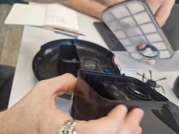
- With the top cover now removed we can remove the clipping lid holding the dust box inside which can also be lifted out and removed.
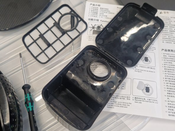
- With the dust box removed we can open the latching lid and remove the dust filter by lifting it up from the provided tabs.
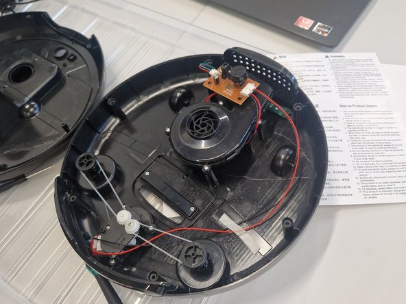
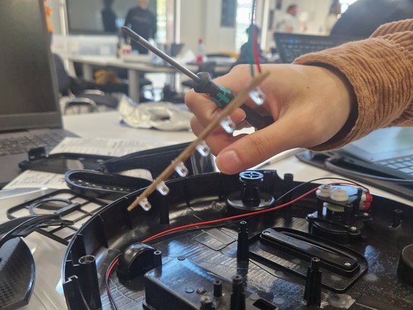
- Back in the internals of the vacuum all located in the bottom cover, the sweeper's drive belts can be then removed easily as they have slack - use the shaft of the screw driver if there are difficulties removing them.
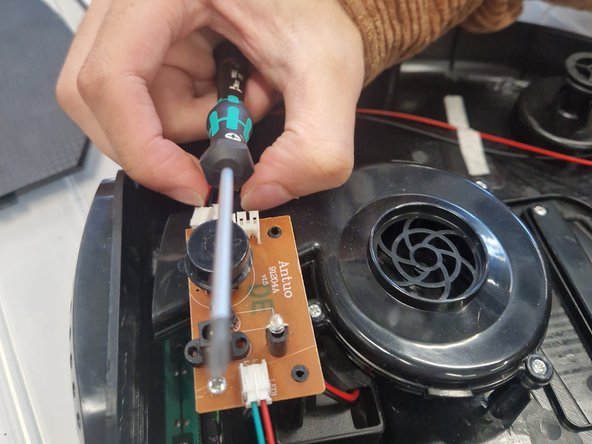
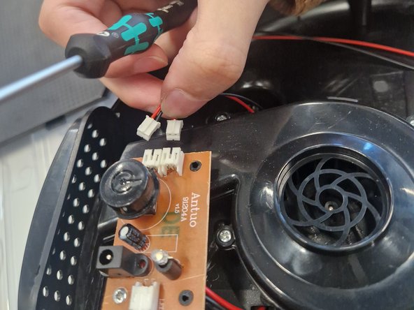
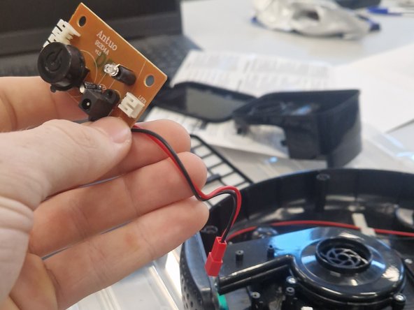
- Carefully using your fingers, the a flat head screwdriver or recommended tweezers, remove the three JST connectors from the PCB which connect the impeller, drive motor assembly and UV light bar.
- With the PCB now disconnected from the components, the PCB can be removed with a Phillips #1 driver. Put this carefully to one side.
- Keep in mind the battery connecter needs to be fed through the battery compartment as it is soldered to the board.
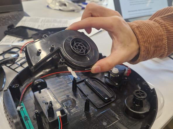
- Using a Phillips #1 driver remove two screws that are holding the impeller assembly to the chassis - you can lift the assembly from the posts.
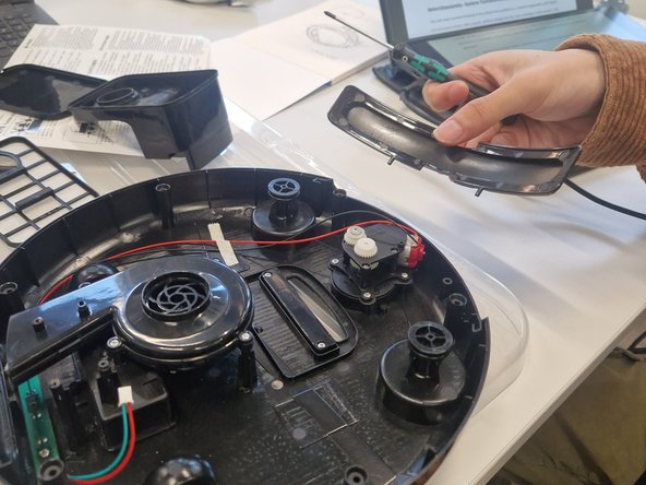
- There are two parts that are loose as they used to be held in by the covers being together.
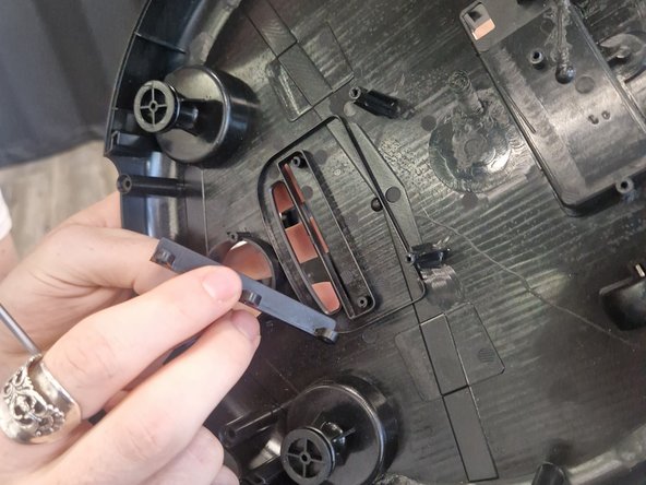
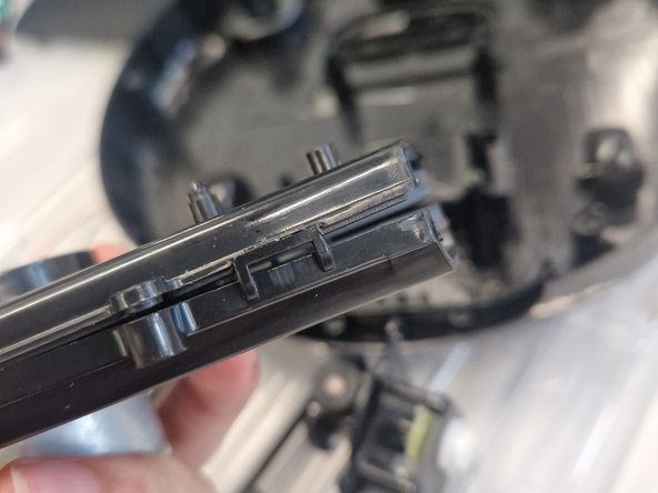
- The exhaust cover and fake sensor bar can be lifted up and placed aside.
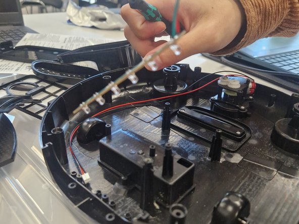
- Using a Phillips #1 driver remove two screws that are holding the UV light bar in place keep this aside.
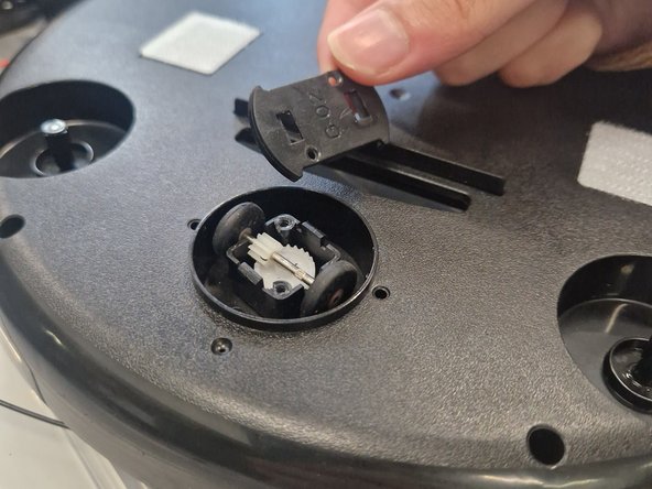
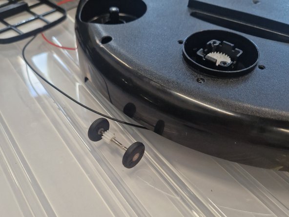
- Using a Phillips #1 driver remove two screws holding the latched cover in place which will reveal the wheels attached to a shaft. You will need to use some tweezers or a flat head driver to carefully release the clips.
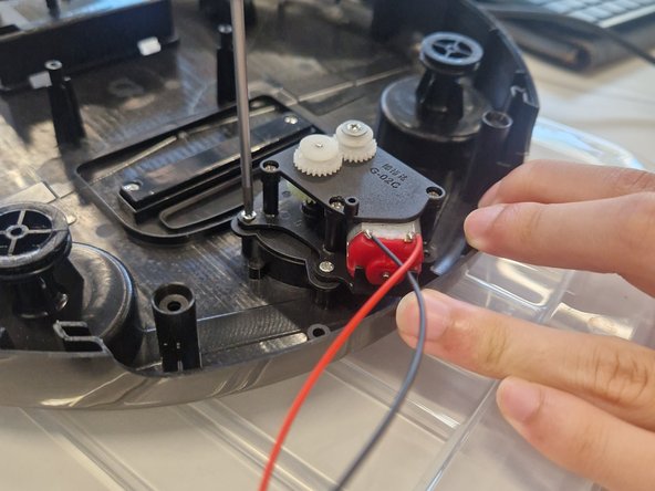
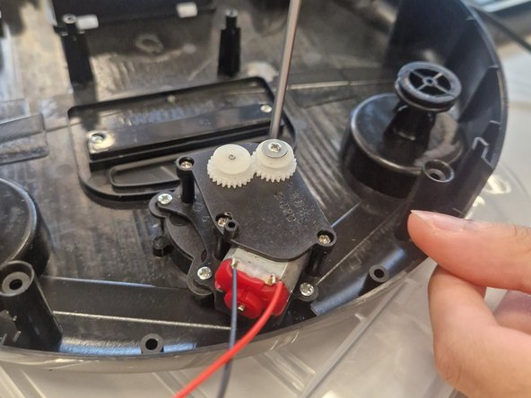
- Using a Phillips #1 driver remove 4 screws holding the driver motor assembly in place - lift this up and keep it aside.
- Using a Phillips #1 driver, remove two screws securing the rubber seal that creates a tight seal with the floor for the suction. This can be easily removed from it's location.
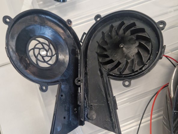
- The Impeller assembly can be teared down even further for access such as maintenance or cleaning.
- There are a few plastic clips that need to be carefully unlatched - use a flat head driver or a shim to do this. Take extra caution as some clips might be brittle and will snap with excessive force.