Airvantage 5” Standard Series Non-Vacuum Vanes Replacement
ID: 178973
Description: Replacing the vanes of a 5” Standard Series:...
Steps:
- Use a 24 mm wrench to remove the pad from the housing.
- Clean off the sander.
- Clamp the sander's housing at a slight angle in a table vise.
- Place a prying tool against the orbit shaft balancer's ridge.
- Gently tap the prying tool with a hammer counterclockwise to unscrew the main body from the shell.
- When hammering against the orbital shaft balancer's ridge, it should twist like so.
- Remove the jaw faces of your table vise and place the main body into the clamp on the edges by the front endplate.
- Place a pointed chisel directly in the middle of the orbit shaft balancer.
- Use gentle to moderate strength to hammer out the shaft balancer.
- If you have a bearing puller you may use the tool to remove the balancer as well, and for this tool the vise is not necessary. Simply mount the puller on the front endplate and twist the lever to free the shaft balancer.
- When hammering the orbital shaft balancer, the shaft balancer should be pushed out like so.
- When the orbit shaft balancer is removed, it will come apart in four separate pieces. The rotor is where the vanes you will be replacing are located.
- Remove this piece from the rotor and replace the old vanes with your new ones.
- After removing the rotor, the woodruff key will slide out.
- Place this back inside its slot before placing the rotor back onto the orbit shaft balancer.
- Line the rotor up with the indent and gently slide the rotor back into place with the vanes in the rotor.
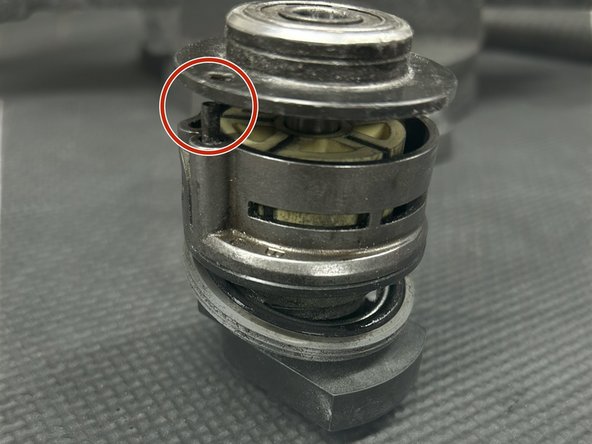
- Place the cylinder assembly part on the front endplate, making sure to line up the holes in both pieces to allow adequate air flow.
- Place the rear endplate on top of the cylinder assembly, again lining up the hole in the rear endplate to the tube in the cylinder assembly.
- Gently hammer the pieces together.
- Take the head of a 3/8 wrench and use the hammer to gently push the bearing into the shaft to secure the main body.
- Make sure to not press the body too tightly together as it may have issues with airflow. The orbit shaft balancer must be able to spin with ease.
- You are now able to follow steps 1 and 2 backwards to reattach the main body to the housing and pad to continue to use your orbital sander.