Sony TCM-450 Microphone Input and Audio Output Replacement
ID: 179088
Description: iFixit Soldering Guide iFixit Desoldering Pump...
Steps:
- Remove the two 3.5 mm Phillips #00 screws from the bottom of the device.
- Caution: Ensure the device is off and unplugged if using the power adapter, as it is unsafe to remove the cabinet while on and will cause damage and potential harm to the user.
- Open the lid, and carefully remove the two 9.7 mm Phillips #0 screws from the inside of the front cabinet.
- Exercise caution while removing these screws, as damage to essential parts may occur and other minor damages may occur if the screwdriver slips.
- Open the battery cover, and gently remove the back cabinet with the iFixit Opening tool.
- The device will make a popping sound when removing the back cabinet. The back cabinet may feel as if it is not loose. However, as long as the back cabinet looks disconnected from the lid, it is safe to remove.
- Carefully desolder each connection and gently remove each connected wire.
- If you are unfamiliar with desoldering and soldering, please consult the iFixit Soldering Guide.
- Make sure the soldering iron is 50 watts as 30-40 watt soldering irons will not melt the solder on the PCB.
- Carefully desolder the next set of connections and gently remove the connected wires.
- Carefully desolder the last two groups of connections and gently remove the wires.
- Caution: Desolder all three marked connections at once before attempting to remove the wires, as they will not fully disconnect and cause damage to the device.
- Carefully remove the three inner screws as shown from the circuit board to loosen it.
- Remove the following screws in this order:
- A 3.4 mm Phillips #00
- A 4.6 mm Phillips #00
- A 9.7 mm Phillips #0. To remove this screw you must lift the PCB at the same time.
- Lift the PCB from the device.
- Make sure not to pull out any wires while lifting the board, as it could cause damage to the device.
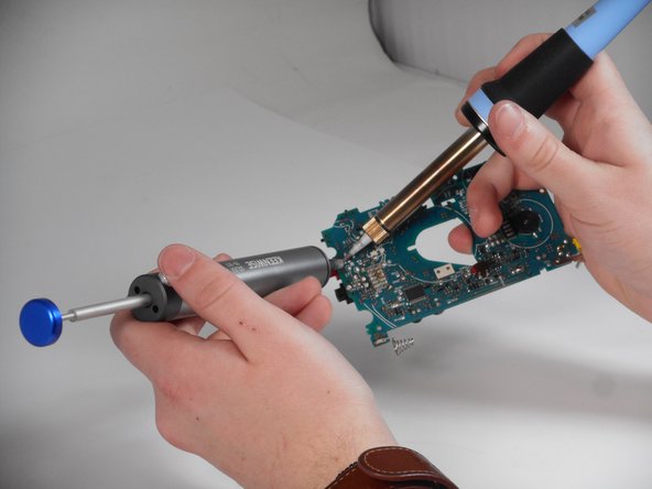
- For both the microphone input and audio output, use a desoldering pump for all three solder points. Use the technique here for all of the soldering points.
- To use the desoldering pump create a suction over the solder point and after the solder has melted press the button on the pump like shown in pictures.
- If you are unfamiliar with desoldering pumps, please consult the iFixit Desoldering Pump Guide.
- Desolder the first and second point connecting the audio output port.
- There will be 2 Solders with white lines under the solders and a label of SP these are speaker solders you do not need to solder/desolder them for this guide.
- There are resistors near this piece be careful not touch them with the soldering iron or you will have to put them back in place using the soldering iron.
- Desolder the third and fourth point connecting the audio output port.
- After removing all of the solder, gently remove the audio output.
- There are resistors near this piece do not touch them with soldering iron or you will have to put them back in place using the soldering iron.
- There will be 2 Solders with white lines under the solders and a label of SP these are speaker solders you do not need to solder/desolder them for this guide.
- If the device does not feel like it can be removed there may still be solder on the audio output. You will need to go back to the previous step.
- Desolder the first solder point connecting the microphone input port.
- After removing all the solder then gently remove the microphone.
- There will be 2 Solders with white lines under the solders and a label of SP these are speaker solders you do not need mess with them for this guide.
- There are resistors near this piece, do not touch them with soldering iron or you will have to put them back in place using the soldering iron.
- If the device does not feel like it can be removed there may still be solder on the microphone input. You will need to go back to the previous step.