Dell Inspiron 1420 Disassembly
ID: 179112
Description: This guide shows how to fully extract the Dell...
Steps:
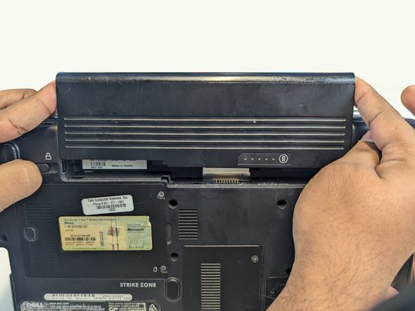
- Press both indicated locks on the bottom side of the laptop to release and remove the battery.
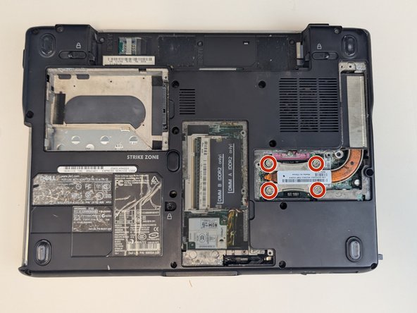
- Loosen and remove indicated screws on the back panel using a Phillips #1 screwdriver.
- Back cover screws
- These screws are a different length than the others and can be stored separately for reassembly.
- Hard drive cover screws
- RAM cover screws
- CD drive cover screw
- Heat sink cover screws
- Remove the hard drive cover.
- Pull the tab in the direction of the arrows to remove the hard drive.
- Using a screwdriver, slide out the CD drive bracket enough for it to be grabbed.
- Remove CD drive from housing.
- Remove RAM cover.
- Pull the metal tabs above and below the RAM outward and remove both RAM sticks.
- Remove the heat sink cover.
- Using a Phillips #1 screwdriver, loosen and remove screws from heat sink.
- Remove the heat sink.
- Using a flathead screwdriver, quarter turn the screw anticlockwise to release the CPU.
- Gently lift the CPU out of the housing.
- The pins on the bottom of the CPU are very fragile and will not function if any are bent.
- Using a Phillips #1 screwdriver, unscrew and remove bracket.
- There may be a card along with the bracket in your machine. If there is, unplug and remove this card as well.
- Using a Phillips #1 screwdriver, loosen and remove the indicated screws.
- Use a spudger to pry off the control panel.
- Use a spudger to pry off the hinge covers.
- Using a Phillips #1 screwdriver, loosen and remove the keyboard screws.
- Gently lift keyboard to reveal blue ribbon connection.
- Use a spudger to flip the blue ribbon lever and release the keyboard.
- Using a Phillips #1 screwdriver, remove the screw holding in the Wi-Fi card.
- Unplug cables connected to Wi-Fi card.
- Slide Wi-Fi card out of connection to remove.
- Using a Phillips #1 screwdriver, loosen and remove control panel screw.
- Carefully pull up control panel. Being sure to keep the cable attached, set to the side.
- Pull the blue tab up to release the monitor.
- Remove monitor.
- Using a Phillips #1 screwdriver, remove remaining screws from cover panel.
- Using a spudger, disconnect control panel motherboard cable.
- Using a spudger, flip up blue lever and disconnect touchpad cable.
- Lift off cover panel.
- Using a Phillips #1 screwdriver, loosen and remove screws from motherboard.
- Disconnect the indicated cables from the motherboard.
- Using a Phillips #1 screwdriver, remove screw.
- Disconnect indicated cable and remove SIM board.
- Slide memory card holder out of housing.
- Flip laptop over to show backplate.
- Loosen and remove modem card screw using a Phillips #1 screwdriver.
- Remove modem card.
- Flip laptop over and gently pull motherboard away from backplate.
- Disconnect the indicated connection to release the motherboard.