HP Pavilion Slimline s5-1224 Teardown
ID: 180181
Description: Special Note: The computer's interior houses...
Steps:
- Make sure to unplug the machine and press the power button to discharge any remaining electricity.
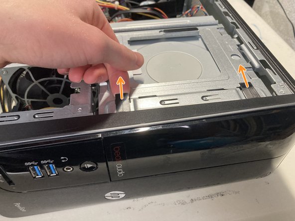
- Place the computer on its side, with the HP logo and fan vent facing up, as shown.
- On the back of the machine, unscrew the rear screw securing the side plate. You should be able to do this with your hand.
- Using the handle, pull the plate towards the back of the machine to reveal the inside.
- Pull up the three clips that hold the faceplate to the computer with your fingers.
- The third clip on mine broke off, so be careful!
- Pull out on the faceplate to remove it.
- Push up on the optical disc drive to get access to the cables.
- Unplug the center power cable between the two other cables on the ODD.
- Unplug the right Serial ATA (SATA) data cable.
- Unplug the leftmost cable.
- This cable was quite hard to pull out, so you may need to get some pliers to remove it.
- Don't grab the cable while unplugging, as this can damage the connection.
- This cable connects the ODD to the "Eject" button on the outside of the machine.
- Remove the right-side screw holding the ODD in place.
- Make a note of which screw hole the screw came out of. Mine came out of the "1" hole, but yours might be different.
- Slide the ODD out, using your fingers to push forward from the back.
- The disc drive is manufactured by Hewlett-Packard, model number DH-16ACSH. It can read and burn DVD/CD-RW discs, including dual-layer discs.
- Unscrew the three screws holding the HDD in place.
- There are three screws; two are outside near the top, and the other is inside the case near the top of the motherboard.
- Pull up the back of the HDD to loosen it.
- Use both hands to pull up the HDD to pull it out of the cavity.
- Don't pull out the HDD completely, as it is still connected to cables.
- Unplug the power cable on the left-hand side.
- Unplug the SATA data cable right next to the power cable.
- The drive is a Seagate Barracuda 7200 RPM 1 TB SATA disk, model ST-1000DM003.
- Make sure you are grounded using an ESD Grounding Strap or other grounding method before touching the RAM. Failure to do so may result in damage to the RAM.
- To learn more about ESD and proper grounding methods, read this excellent iFixit article.
- Push the four clips outward, and pull the RAM sticks straight out.
- The top stick is a Kingston 2 GB module labeled as HP655409-150-HYCG. It has 8 SK Hynix 512 MB chips.
- The bottom stick is a Micron 4 GB module labeled as MT16JTF51264AZ-1G6M1. It has 16 Micron 512 MB chips.
- This PC came with 6 GB of DDR3 1066 MHz RAM.
- Unscrew the four silver screws that hold the heatsink assembly down in a star pattern, as shown, starting with the one marked by the blue circle.
- Do not remove the black screws. These are for holding the fan to the heat sink. The silver screws hold the heat sink against the CPU. Also, the silver screws don't come out, they only unscrew.
- Failure to unscrew the screws a little at a time using a star pattern may result in motherboard damage.
- Unplug the CPU fan power cable located above the heat sink assembly and near the top of the case.
- Remove the heat sink assembly.
- Push the lever holding the CPU down and to the left.
- Open the plate holding the CPU down and remove the CPU.
- The CPU is an Intel Pentium G640 with two cores and a clock speed of 2.8 GHz.
- Unplug the circulation fan power cable.
- You may need to cut the zip tie holding the CPU power cable and the circulation fan's cable together if you wish to remove the fan entirely.
- Unscrew the two screws at the top and bottom of the fan, holding it in place.
- These photos are rotated so they can fit without cropping. The arrow is pointing down towards the case.
- Slide the fan down towards the bottom of the case, then lift it out.
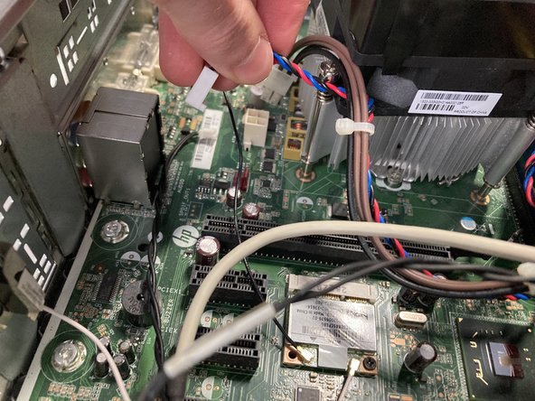
- Unplug the motherboard's power cable on the right-hand side.
- Unplug the CPU's power cable on the left-hand side.
- Unplug the cable right above the SATA ports on the bottom right-hand side of the motherboard.
- This cable connects the power button to the motherboard.
- Remove the two SATA cables.
- Make sure to note which cable comes out of each port. The HDD should be connected to the dark blue "SATA0" port, and the ODD should be connected to the light blue "SATA2" port.
- The dark blue is SATA0, the white is SATA1, the light blue is SATA2, and the yellow is SATA3.
- Unplug the big cable with two cables coming out.
- This cable handles the USB 3 connection coming from the two ports on the front.
- Unplug the white slim cable near the top of the power supply.
- Unplug the fatter orange cable to the left of the other cable.
- You are unplugging different ends of the same cable that handles audio. I assume that this cable connects to an internal USB 3 connection and then sends the audio to a dedicated audio port. (My opinion, so don't quote me on that.)
- Pardon the components you've already removed; I took this photo before I did many of the steps that came before.
- Remove the six screws that hold the motherboard down.
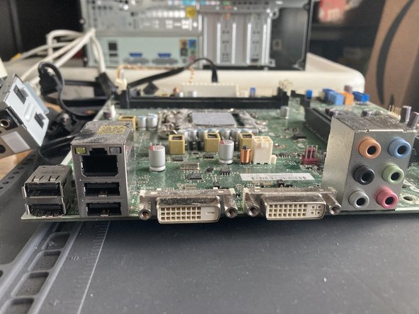
- Pull the motherboard to the left and out to remove it from the case.
- The motherboard is an HP MicroATX board, model H-JOSHUA-H61-uATX-1.00. It has two DIMM slots, one 16x PCI Express port, four PCI Express ports, four integrated USB 2 ports, USB 3 capability, gigabit ethernet, dual DVI video out, dedicated audio out ports, and four SATA connections.
- This motherboard also has a Mini PCI Express slot, which originally wasn't filled. I added a Wifi module that I swapped from another computer, and it works.
- You could probably add a discrete GPU in here using the 16x PCI Express slot, but you should consider the PSU's limitations and other factors before choosing one.
- You can find the motherboard info in the orange circle.
- This motherboard is a prime candidate for upgrades, as it uses standard uATX form factor and PSU connections.
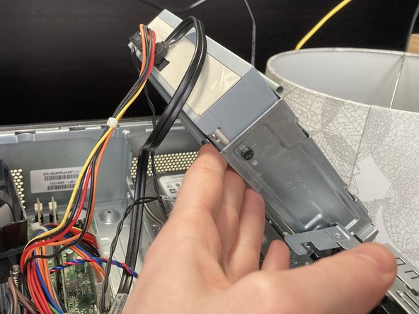
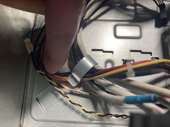
- Pull out all wires under the clip on the right-hand side in front of the PSU.
- Remove the four screws on the back of the machine securing the PSU to the case.
- There is a clip at the front of the PSU that holds it in place. Press it down, and slide the PSU to the right to remove it.
- The PSU is branded by HP but made by Delta Electronics. The PSU has a maximum rating of 220W, which is fairly low by today's standards. The PSU's model number is DPS-220AB-6.
- Unscrew the screw on the front of the machine holding the hub in place. The screw will not come out, just unscrew.
- Unplug the bottom cable on the back of the hub.
- Pull the hub out. See the next step for unplugging the yellow and back cable from the power button.
- Remove the orange, yellow, and black braided cable located underneath the ODD bay, where the HDD goes.
- Follow the cable until you get to the part where it connects to another cable. Unplug them. (You may now fully remove the I/O Hub from the previous step.)
- From inside the machine, undo the clip and remove the power button from the front, threading the cable.
- There are two clips inside the machine for the eject button near the middle. Pinch together the two clips from inside the case and pull the button out through the front.
- The empty computer case! I hope you enjoyed this teardown.