PlayStation 5 Pro USB-C Board Replacement
ID: 180188
Description: Follow this guide to replace the USB-C board in...
Steps:
- Before starting your repair:
- Shut down your PlayStation and unplug all cables and accessories.
- Remove any stands supporting your console and lay it down so the right side is facing up.
- Each console cover is secured with hooks along the rear edge and clips along the front edge.
- To remove a cover, firmly pull up the front edge to release the clips.
- You'll hear distinct "pops" as the clips release.
- Remove the cover.
- Use the same process to remove the three remaining covers.
- To reinstall a cover, place the hooks into their cutouts along the rear edge and firmly press the front edge of the cover into place to re‑engage the clips.
- Use a T8 Torx Security screwdriver to remove the two 21.5 mm‑long screws securing the power supply.
- Flip your PlayStation over.
- Throughout this repair, keep track of each screw and make sure it goes back exactly where it came from.
- Use a Phillips screwdriver to remove the 17.1 mm‑long screw securing the expansion slot cover.
- Use your fingers to lift the expansion slot cover near the notch by the screw hole and remove it.
- Use your fingers to remove the plastic cover hiding the fan cables connector.
- The cover is secured with light adhesive.
- During reassembly, press the piece of plastic back into place to secure it with the leftover adhesive. If it isn't sticking, use strips of double-sided tape to secure it.
- Gently pull the fan cables out from under their plastic clip on the frame.
- Firmly grip the fan cables' white connector head and pull it straight up and out of its socket.
- If you're having trouble, grip the cables just above the connector head, and gently pull.
- During reassembly, align the connector over its socket and push down on the edges with the flat end of a spudger until it slides fully into its socket.
- Use a T8 Torx Security screwdriver to remove the four screws securing the fan:
- One 31.7 mm‑long screw
- Two 21.5 mm‑long screws
- One 11.5 mm‑long screw
- Use your fingers to grab the fan by its vents and lift it straight up to remove it.
- During reassembly:
- This is a good point to clean the fan. Use a clean cloth and some compressed air to remove any dust or dirt.
- Insert the fan so its cables are near their connector.
- A tamper-evident sticker hides one of the right‑side inner shell screws.
- If you live in the U.S., you're protected under the Magnuson–Moss Warranty Act and these stickers are illegal—don't let them intimidate you! Elsewhere, warranty protections differ.
- Use tweezers to peel up the sticker until you can access the screw underneath.
- Use your fingers to unclip and remove the plastic grille near the fan recess.
- Use a T8 Torx Security screwdriver to remove the 10 screws securing the right‑side inner shell:
- Four 18.8 mm‑long screws
- Two 18.6 mm‑long screws
- Four 31.7 mm‑long screws
- Lift the right‑side inner shell straight up and remove it.
- Use a pair of angled tweezers to firmly grip the sides of the CMOS board connector, holding the tweezers as close to the connector as possible to get a good grip.
- Pull the connector straight up and out of its socket to disconnect it.
- If you're having trouble, try rocking the connector side-to-side to loosen it.
- Use your fingers to lift the CMOS board off the small metal nubs and pull it toward the center of your console to remove it.
- If your new board doesn't come with a cable, transfer the original cable to your replacement board.
- Insert a spudger under the metal neck of one of the antenna cable's coaxial connectors and lift straight up to disconnect it.
- Repeat the process to disconnect the other antenna cable.
- During reassembly:
- Use the markings on the board to reconnect the antenna cables to the correct sockets—connect the blue cable to the socket marked RB and the white cable to the one marked RW.
- To reconnect a cable, hold the metal connector head over its socket and press down with the flat end of a spudger until the connector snaps into place. Don't try to force the connector into place. If you're having trouble, reposition the connector and try again.
- Use the point of a spudger to flip up the small piece of white tape securing the antenna cables to the metal shield.
- Use your fingers to de‑route the antenna cables from their clips on the metal shield.
- Move the antenna cables over the side of your PlayStation so they're out of the way.
- Thermal paste bonds the bottom heat sink fins (closest to the power button) to the metal shield. Depending on the age of your device and condition of the thermal paste, separating the heat sink may take some force.
- Insert the flat end of a spudger under the bend in the copper pipes, near the heat sink's bottom edge.
- Use your spudger to pry up the heat sink, applying steady pressure to separate it from the thermal paste.
- If the heat sink doesn't fully separate, use your spudger to pry up the bottom edge on the other side of the metal fins.
- Grip the heat sink by its copper pipes and remove it.
- Don't grip the sharp, metal fins on the heat sink.
- During reassembly:
- Before removing any of the old thermal paste, note the location and quantity of thermal paste on the metal shield. This way you'll know how much to use when replacing it.
- Use the flat end of a spudger to scrape up and remove as much of the old thermal paste as possible.
- Remove all the remaining thermal paste and its residue with high‑concentration (>90%) isopropyl alcohol and a microfiber cloth.
- Apply new thermal paste where the old paste was.
- Firmly push the heat sink into place.
- Use a T8 Torx Security screwdriver to remove the six screws:
- One 11.5 mm‑long black screw securing the main board assembly
- One 28.7 mm‑long screw securing the interconnect cable cover
- Four 7.5 mm‑long screws securing the interconnect cable cover
- Remove the interconnect cable cover.
- Use the flat end of a spudger to push down the metal bar on the interconnect cable socket.
- With the metal bar held down, use your fingers or tweezers to grip the plastic pull tab and slide the cable straight out of its socket.
- During reassembly, insert the interconnect cable into the socket until it snaps into place.
- The power supply is connected to the bottom of the main board assembly by metal prongs that plug into the bottom left corner.
- Lift the bottom left corner of the main board assembly off its gray plastic post. Keep the assembly lifted for the next step.
- Your PlayStation's plastic housing will likely flex while lifting the assembly.
- Keep the main board assembly raised with one hand.
- With your free hand, insert your finger between the assembly and power supply.
- Push down on the power supply and lift the assembly to separate them.
- It'll take a significant amount of force to separate the two.
- During reassembly, press down firmly on the bottom left corner of the main board assembly to fully connect it to the power supply.
- Do not grab the main board assembly by the copper heat pipes or its fins, as they can easily be damaged.
- Firmly secure the plastic housing with one hand.
- With your free hand, grab the upper edge of the main board assembly and lift it out of the plastic housing.
- During reassembly:
- Make sure the interconnect cable doesn't get stuck under the main board assembly when lowering it into place.
- Lower the assembly into its recess so its prongs go into their socket on the power supply and the two cutouts go over their alignment posts.
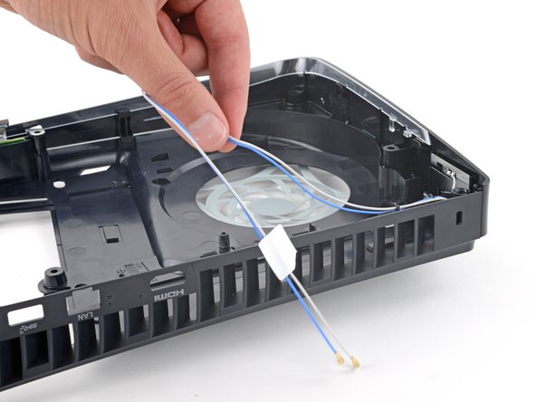
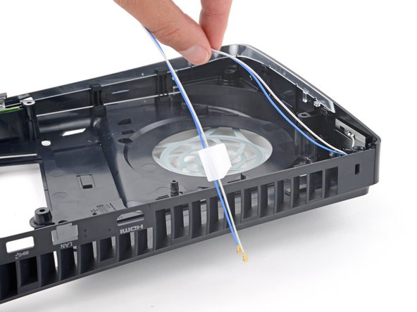
- Pull both antenna cables up and out of their clips along the rear edge of your PlayStation.
- During reassembly, place the cables back into their clips on the rear edge of the frame.
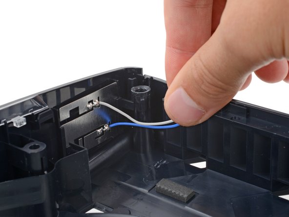
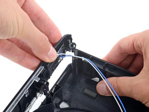
- Push both antenna cables down and out from under their clip on the top right corner of the plastic housing.
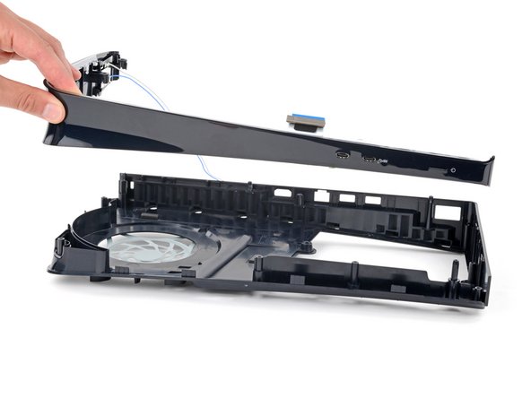
- With one hand, secure the right edge of the plastic housing.
- With your free hand, firmly lift the top edge of the front trim to release its three plastic clips.
- During reassembly, push the front trim onto the frame so the clips snap into place.
- Lift the front trim straight up and remove it.
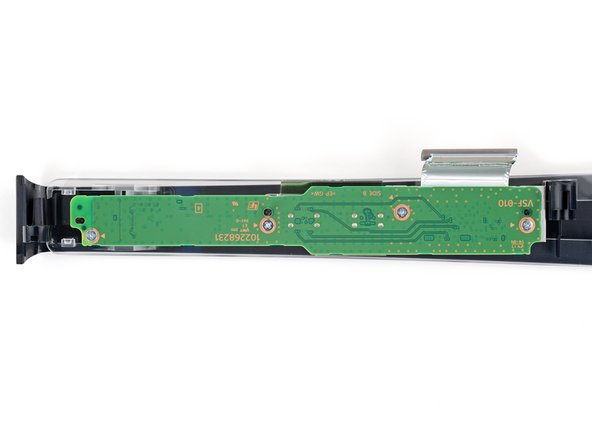
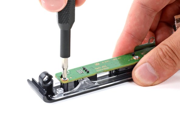
- Secure the front trim against your workspace so the USB-C board screws are facing up.
- Use a Phillips screwdriver to remove the four 6.6 mm‑long screws securing the board.
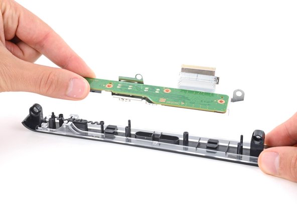
- Lift the USB-C board straight up and remove it.
- During reassembly:
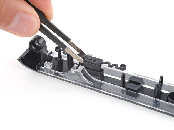
- Before putting the board into place, make sure the small, plastic power button is in its recess.
- Set the board into place so its cutouts go over their alignment pegs on the front trim and the USB-C ports go into their recesses.