How to Replace the SSD in your Mac mini (2024)
ID: 180199
Description: Use this guide to replace the SSD, or flash...
Steps:
- Fully shut down your Mac mini and unplug all cables from it.
- Flip over your Mac mini and place it on a clean, flat surface to avoid scratching the chassis.
- Using the Jimmy or other metal tools during this step could scratch the aluminum chassis; however, it's the simplest way to perform this step. Follow the alternate instructions to avoid scratching the aluminum.
- Insert a Jimmy into the gap between the bottom cover and the chassis.
- Pry up the bottom cover to create a gap.
- Alternatively, you can insert the point of a spudger into one of the plastic vent holes and pry up to create a gap big enough to insert an opening pick into.
- Keep the Jimmy inserted under the bottom cover.
- Insert an opening pick into the gap created by the Jimmy.
- Remove the Jimmy.
- Slide the opening pick along the bottom cover until you feel it snag on a pin.
- There are four pins total—one at each corner of the bottom cover.
- Twist the pick to lift the pin out of its slot.
- Continue sliding and prying with the pick along the perimeter of the bottom cover to release the remaining pins.
- Don't insert the pick more than an inch when sliding near the power button, as you risk damaging the cable.
- During reassembly, press along the perimeter of the bottom until you hear and feel all four pins click back into place.
- Don't remove the bottom cover, as it's still connected to the Mac mini with a cable.
- Lift the edge of the bottom cover opposite the power button and flip it over to expose the power button cable.
- The power button cable is very fragile! You don't have to disconnect it to access the internals— but it will require you to keep the bottom cover propped up.
- To disconnect the cable and remove the bottom cover, follow the next two steps.
- If you don't disconnect the cable, prop up the bottom cover to prevent straining the cable and skip the next two steps.
- Grip the power button cable close to the head and pull it away from its socket to disconnect it.
- Remove the bottom cover.
- Throughout this repair, keep track of each screw and make sure it goes back exactly where it came from.
- While the Mac mini uses Torx Plus screws, standard Torx bits work. Make sure to apply constant, downward force to prevent stripping.
- Use a T5 Torx screwdriver to remove the eight 3.4 mm‑long screws securing the inner plate.
- Insert the point of a spudger into one of the clips' slots on the inner plate.
- Pry up the inner plate enough so you can grip the edge along the same side as the headphone jack.
- Pull the inner plate away from the chassis to slide it out from under the lip on the heat sink.
- During reassembly, slide the inner plate back under the heat sink and press along its edges to secure it in the chassis.
- Don't remove the inner plate, as it's still connected to the Mac mini by a cable.
- Lift the inner plate and flip it over the edge of the chassis. Let it rest against the chassis.
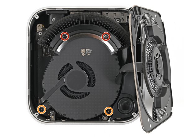
- Remove the four screws securing the fan:
- Two 2.4 mm‑long Torx Plus 3IP screws
- Two 7.9 mm‑long Torx Plus 5IP screws
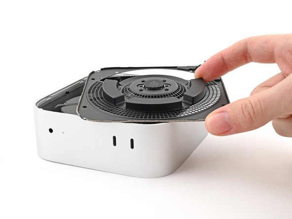
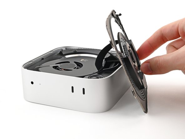
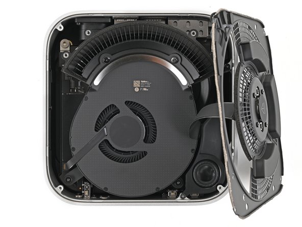
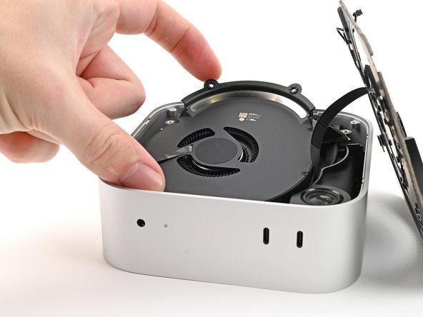
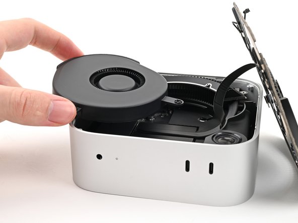
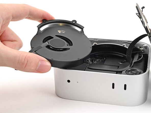
- Lift the fan out of its recess in the chassis and flip it over to expose its wire and connector.
- Let the fan rest on the chassis and heat sink.
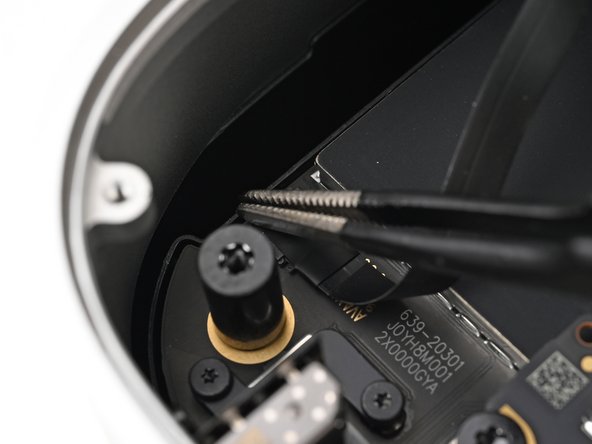
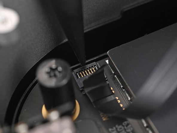
- Use tweezers to peel back the tape covering the fan ZIF connector.
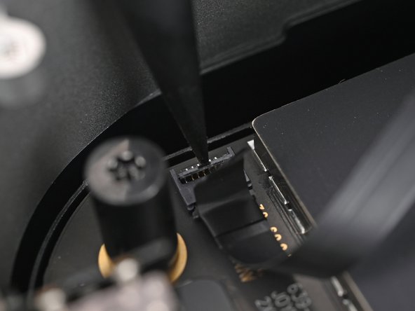
- Use the point of a spudger, or your fingernail, to flip up the locking tab on the fan ZIF connector.
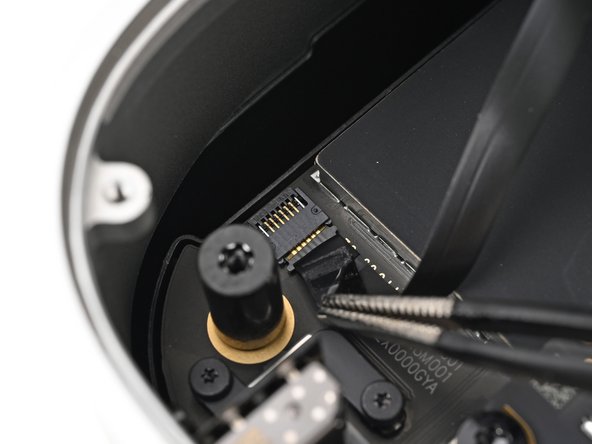
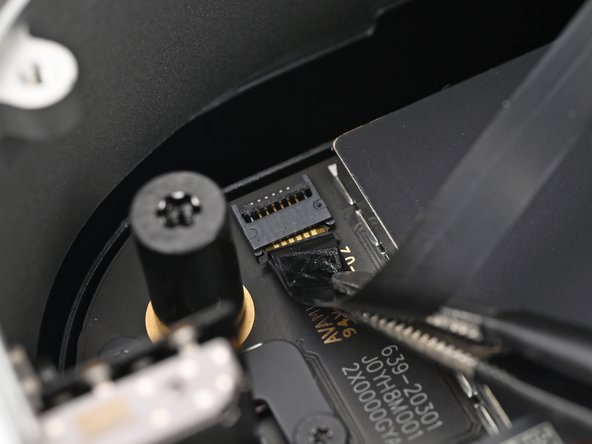
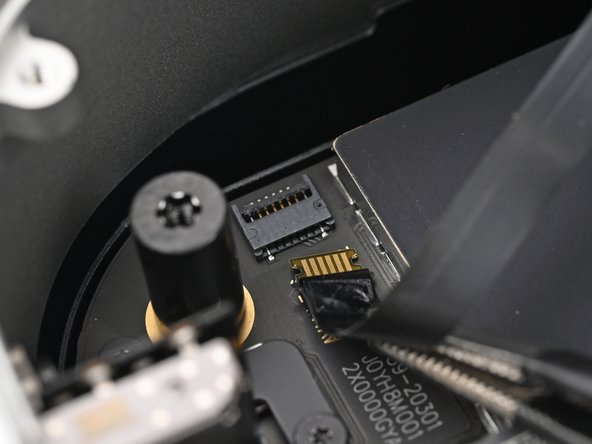
- Use tweezers, or your fingers, to slide the ZIF connector straight out of its socket.
- Remove the fan.
- Use a Torx Plus 8IP screwdriver to remove the 4.1 mm‑long screw securing the SSD.
- Insert the point of a spudger into one of the holes along the bottom edge of the SSD.
- Use the spudger to pull the SSD away from its socket, alternating sides as necessary, until it's fully disconnected.
- Grip the corner of the SSD, tilt it up against the headphone jack, and lift it out of its socket.
- During reassembly, insert the SSD at an angle and gently wiggle it into place until it sits flat to the logic board.