iPhone 16 Pro Logic Board Replacement
ID: 180260
Description: Follow this guide to replace the logic board in...
Steps:
- Allow the phone's battery to drain below 25%, as a charged lithium-ion battery is a potential safety hazard.
- Unplug any cables from the phone.
- Hold the power and either volume buttons and slide to power off the phone.
- If the screen or back glass is badly cracked, lay overlapping strips of packing tape over the glass to protect yourself and make disassembly easier.
- Make sure there's a smooth area near the bottom edge that's big enough for a suction cup to stick to.
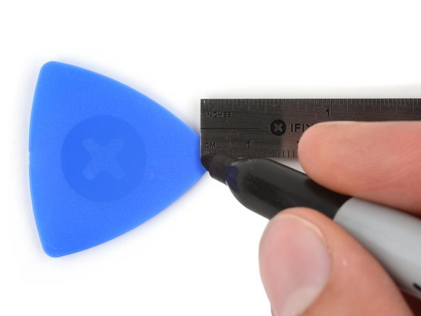
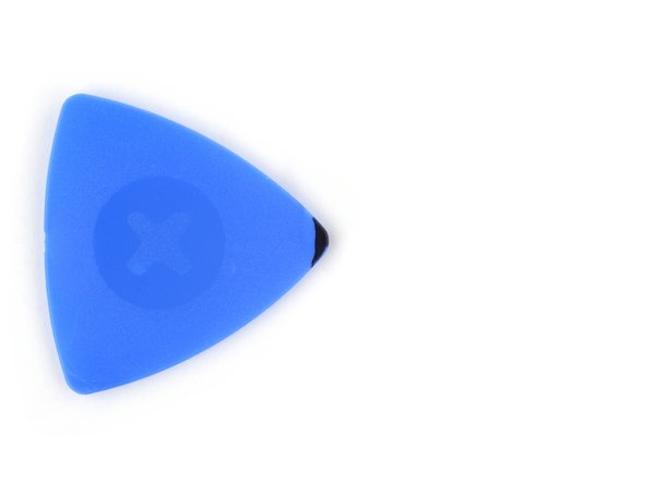
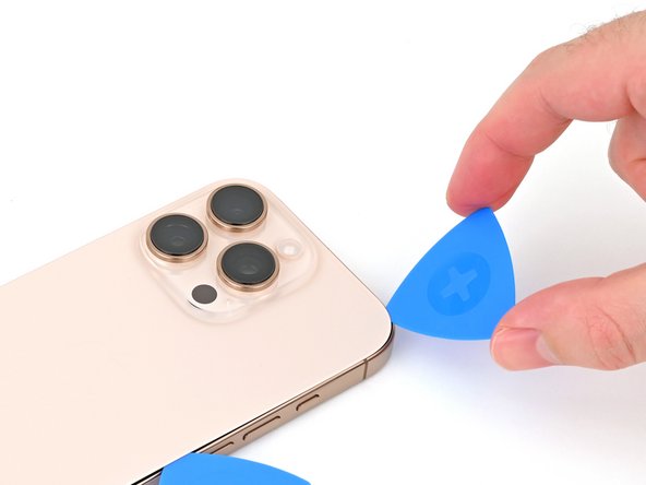
- If inserted too far, an opening pick can damage your device. Follow this step to mark your pick and prevent damage.
- Measure 3 mm from the tip and mark the opening pick with a permanent marker.
- You can also mark the other corners of the pick with different measurements.
- Alternatively, tape a coin to a pick 3 mm from the tip.
- Use a P2 pentalobe screwdriver to remove the two 7.4 mm‑long screws on either side of the USB-C port.
- Apply a heated iOpener to the bottom edge of the back glass for two minutes.
- Alternatively, you can use a hair dryer or heat gun to heat the bottom edge of the back glass until it's hot to the touch.
- Be careful not to heat the phone hotter than this—the battery is susceptible to heat damage.
- Apply a suction handle to the bottom edge of the back glass, above the USB-C port.
- Pull up on the handle with a strong, steady force to create a gap between the back glass and the frame.
- Insert the tip of an opening pick into the gap.
- As you slice the adhesive securing the back glass in the next steps, be careful of the following areas:
- There's a delicate cable connecting the back glass to the phone, right next to the volume up button. Don't insert your pick here to avoid slicing the cable.
- There are multiple spring contacts around the perimeter of the phone. Be extra careful not to insert your pick deeper than suggested in each step to avoid bending these contacts.
- If you damage the spring contacts, gently bend them back with a spudger or opening pick so they align with their gold contact pads on the back glass.
- Don't insert your pick deeper than 5 mm on the bottom edge to avoid damaging the spring contact.
- Slide your pick back and forth along the bottom edge to separate the adhesive.
- Leave your pick inserted in the bottom right corner to prevent the adhesive from resealing.
- Heat the right edge of the back glass until it's hot to the touch.
- Slide your pick around the bottom right corner and halfway up the right edge, or until you feel a hard stop at a clip securing the back glass.
- Don't slice near the volume buttons to avoid damaging the wireless charging/flash cable.
- Leave this pick inserted to prevent the adhesive from resealing.
- Heat the left edge of the back glass until it's hot to the touch.
- Insert a second opening pick at the bottom edge.
- Slide the second pick around the bottom left corner and along the left edge of the screen to separate the adhesive and release the metal clips.
- You'll hear and feel the metal clips release as you pass them.
- Leave this pick inserted at the top left corner to prevent the adhesive from resealing.
- Heat the top edge of the back glass, including the area around the volume buttons, until it's hot to the touch.
- Don't insert your pick deeper than 3 mm along the top edge to avoid damaging the spring contacts.
- Slide your opening pick across the top edge and around the top right corner to the volume up button to separate the adhesive.
- You'll hear and feel clicks as the top two clips release.
- Don't try to fully remove the back glass just yet—it's still attached with a delicate ribbon cable. Follow the next few steps to remove it safely.
- If the back glass doesn't swing open easily, don't force it—go back around the perimeter with your pick to check for missed sections of adhesive or stuck clips.
- You may need to lift the back glass up slightly before swinging it open to fully disengage the clips.
- Gently swing open the back glass towards the volume buttons.
- Support the back glass with a clean, sturdy object like a small box to avoid straining the cable.
- Remove the opening picks.
- Consider using polyimide tape to protect the rear camera lenses while you're working inside the phone. Don't push against the lenses to avoid damaging the delicate stabilizers.
- Use a tri-point Y000 screwdriver to remove the three screws securing the lower connector cover:
- Two 1.2 mm‑long screws
- One 1.0 mm‑long screw
- Use tweezers or your fingers to pick up and remove the lower connector cover.
- Use the point of a spudger to pry up and disconnect the battery press connector.
- Use a tri-point Y000 screwdriver to remove the four screws securing the upper connector cover:
- Two 1.0 mm‑long screws
- One 1.2 mm‑long screw
- One 1.6 mm‑long screw
- Use tweezers or your fingers to pick up and remove the upper connector cover.
- Use the point of a spudger to pry up and disconnect the back glass press connector.
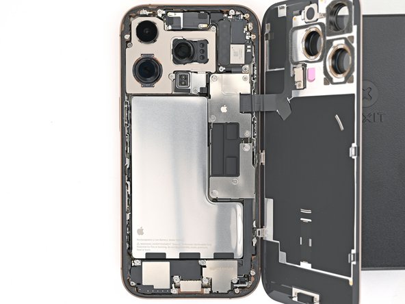
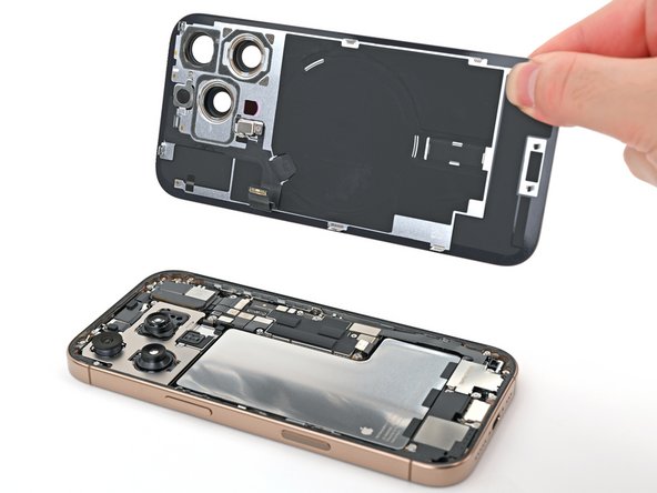
- Lift the back glass off the frame and remove it.
- The 5G mmWave antenna is only in United States and Puerto Rico iPhone 16 Pros (model A3083). For all other models, skip the next four steps.
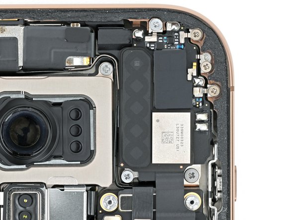
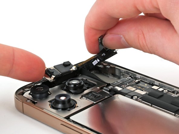
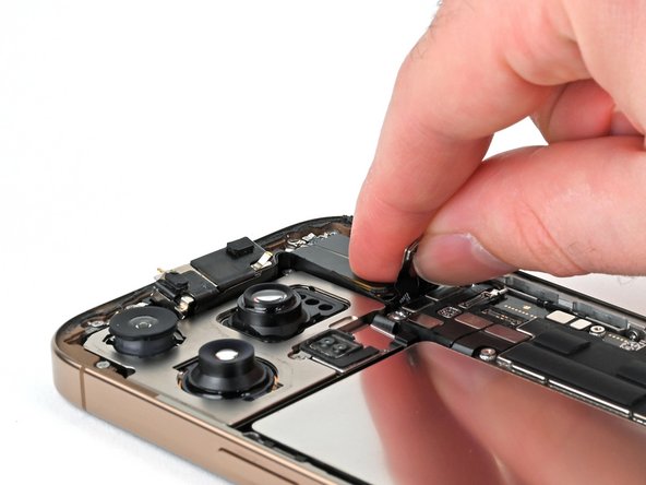
- Use the point of a spudger to pry up and disconnect the earpiece speaker and 5G mmWave antenna press connectors, located on the top right corner of the logic board.
- Use a Phillips screwdriver to remove the six screws securing the earpiece speaker:
- Three 1.2 mm‑long screws
- Two 1.8 mm‑long screws
- One 1.7 mm‑long screw
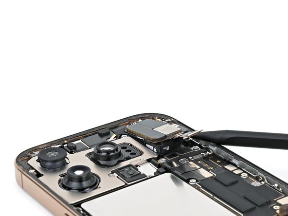
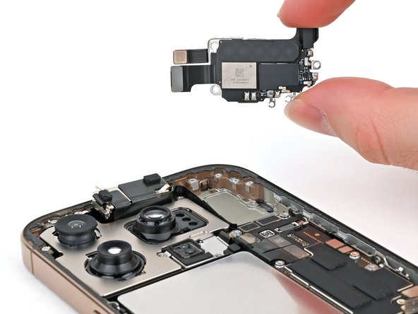
- Insert the point of a spudger in the bottom-right corner of the earpiece speaker and pry it up to remove it.
- You may feel some resistance near the top edge, where the speaker gasket seals against the frame. Pull the speaker out gently to release the seal.
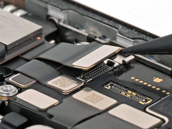
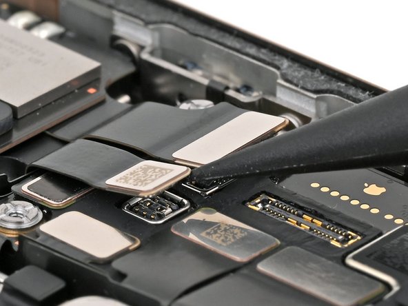
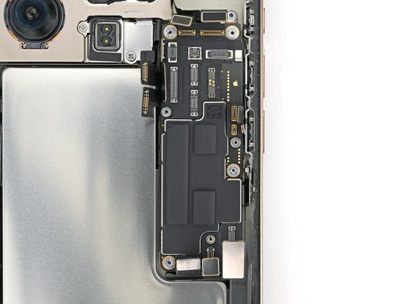
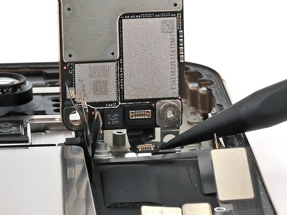
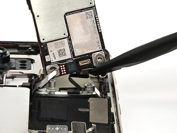
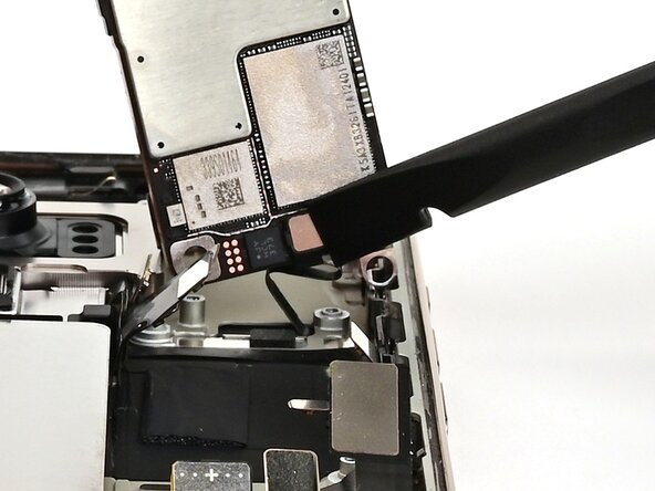
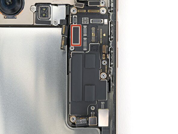
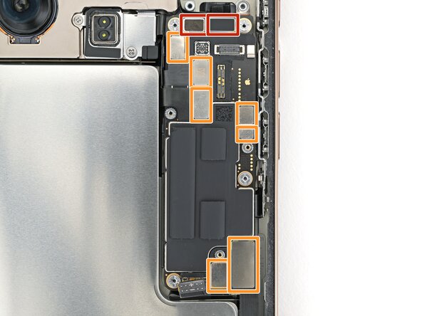
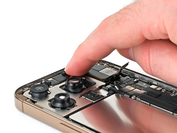
- Use a spudger to pry up and disconnect the press connectors from the top of the logic board:
- Seven silver connectors
- Three black connectors
- One of the black connectors is under the two silver connectors on the left edge of the board.
- Standoff screws are best removed using a dedicated standoff screwdriver or driver bit. In a pinch, a small flathead screwdriver will do the job—but use extra caution to ensure it doesn't slip and damage surrounding components.
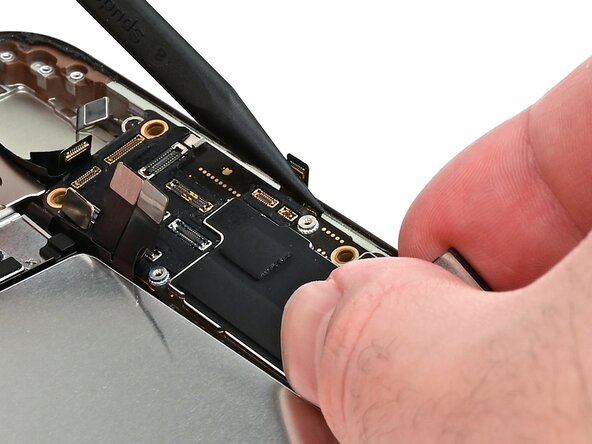
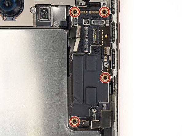
- Use a standoff screwdriver to remove the four screws securing the logic board:
- Two 4.5 mm‑long screws
- One 3.4 mm‑long screw
- One 4.2 mm‑long screw
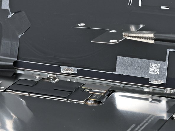
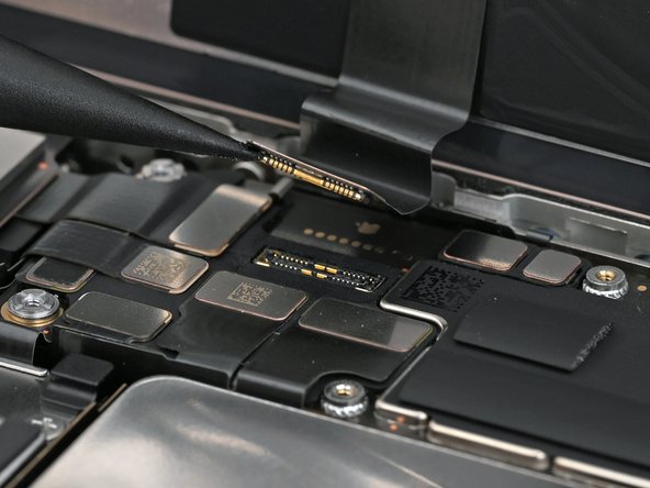
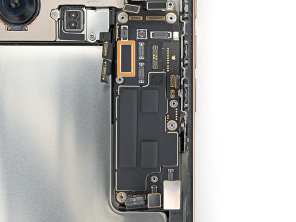
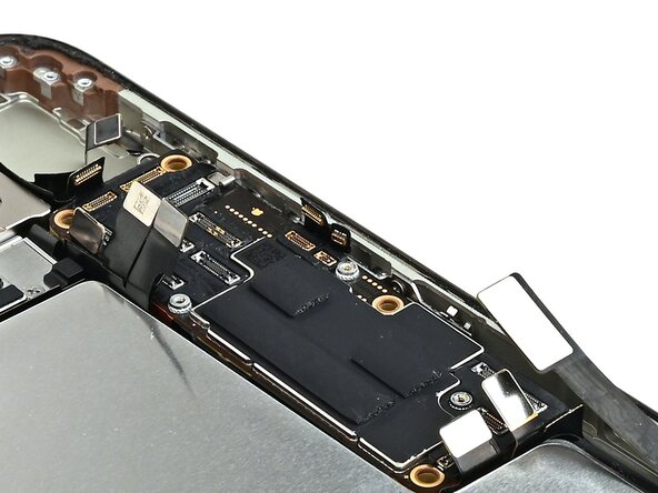
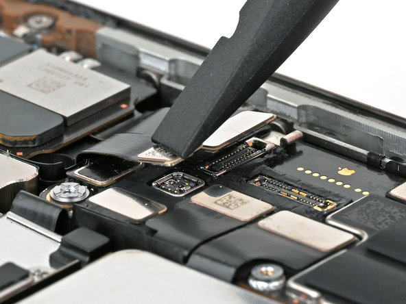
- This image shows the display connector underneath the logic board with the board removed. The next two steps show how to disconnect this connector from the logic board.
- If the iPhone has a SIM card tray, eject it before you proceed.
- USA model iPhones (A3084) don't have a SIM card tray.
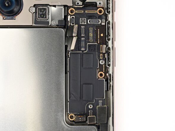
- Make sure all the connectors are disconnected from the top of the logic board before proceeding.
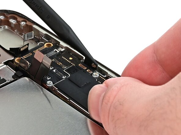
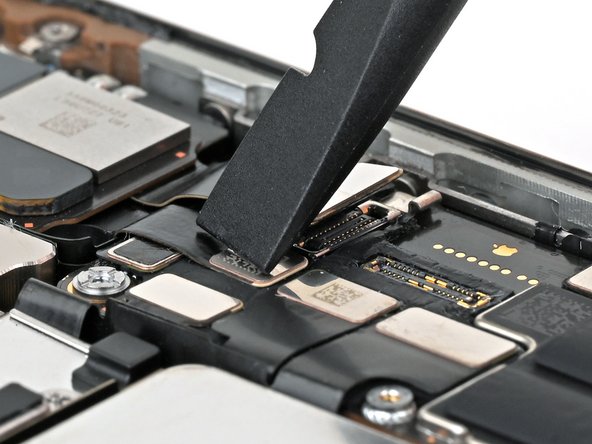
- Insert the flat edge of an opening pick between the battery and the logic board. Hold the pick in place with your fingers.
- Don't remove the logic board yet. There's still a cable connected to the bottom side.
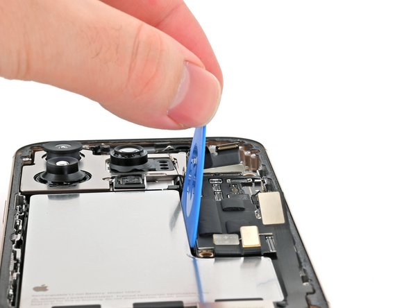
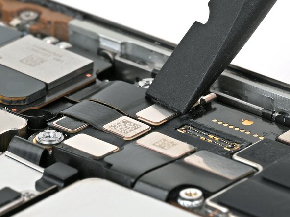
- Insert the flat end of a spudger underneath the right edge of the logic board.
- Gently pry with the spudger and opening pick to lift the logic board and disconnect the screen connector.
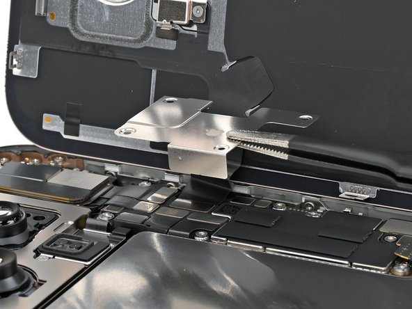
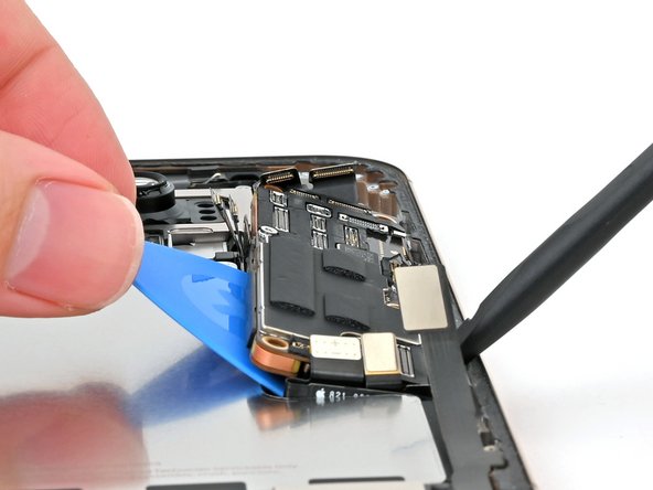
- Pick up the bottom edge of the logic board, flip it up towards the top of the phone, and hold it steady vertically.
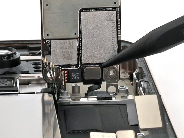
- Use the point of a spudger to pry up and disconnect the front sensor connector from the underside of the logic board.
- Remove the logic board.
- Hold the logic board above the phone so the socket on the underside of the board is close to the front sensor cable.
- Use your finger or a spudger to press the front sensor cable connector into its socket on the logic board until it clicks into place. Don't try to force the connector into place. If you're having trouble, reposition it and try again.
- Use your fingers or a spudger to gently hold all the loose press connectors out of the way so you can lay the logic board in place.
- Lay the logic board in its recess.
- You can't directly connect the display connector to the bottom of the logic board without removing the screen, but you might successfully connect it by screwing the logic board in place. Be sure to test your iPhone later in this guide.
- If it fails, work back to this step and try again or follow the screen replacement guide to connect it manually.
- Make sure the logic board rests in place against its screw posts. The posts will properly align the board to the display connector underneath it.
- Use a standoff screwdriver to install the four screws securing the logic board:
- Two 4.5 mm‑long screws
- One 3.4 mm‑long screw
- One 4.2 mm‑long screw
- To connect press connectors like these, carefully align and press down on one side until it clicks into place, then repeat on the other side. Don't press down in the middle. If the connector is misaligned, the pins can bend, causing permanent damage.
- Use your finger or a spudger to connect the press connectors to the top of the logic board:
- Three black connectors
- One of the black connectors is under the two silver connectors on the left edge of the board, and needs to be connected first.
- Seven silver connectors
- Don't connect the battery press connector, labeled with a "+" and "-".
- Insert the top edge of the earpiece speaker into its cutout at a downward angle before pressing it flat to the frame.
- You may have to lift the front camera assembly just enough to get the earpiece speaker in its cutout. Route the antenna and earpiece speaker cables to the right of the front camera cables. Press the front camera into its cutout, then push its cables flush with the rear cameras.
- Use a Phillips screwdriver to install the six screws securing the earpiece speaker:
- Three 1.2 mm‑long screws
- Two 1.8 mm‑long screws
- One 1.7 mm‑long screw
- Use your finger or a spudger to connect the earpiece speaker and 5G mmWave antenna (US only) press connectors, located on the top right corner of the logic board.
- Work around the fragile grounding clips as you're cleaning the frame. If you bend one out of place, gently bend it back with your fingers or tweezers.
- Use blunt nose tweezers or your fingers to remove large pieces of adhesive from the frame perimeter.
- Use a spudger to scrape the adhesive residue off of the frame.
- If the adhesive feels stubborn, apply some heat using a hair dryer or heat gun and try again.
- If you're reusing your back glass, apply a few drops of highly-concentrated isopropyl alcohol (over 90%) to a microfiber or lint-free cloth and wipe around the perimeter to prepare the surface for new adhesive.
- Wrap a lint-free cloth or a coffee filter over the point of a spudger and apply a few drops of highly-concentrated isopropyl alcohol (over 90%) to it.
- Wipe in one direction along the perimeter of the frame to clean the adhesive residue.
- Take your time doing this. A clean frame allows replacement adhesive to lay evenly, ensuring a better bond.
- Lay the adhesive sheet over the frame to determine its proper orientation.
- Use features such as the camera cutout and notches along the top and bottom edges to visualize how the adhesive will lay in the frame.
- Grab the tab in the corner of the adhesive sheet and peel the liner to expose a third of the adhesive.
- The exposed adhesive is very sticky. Don't let it touch anything until you're ready to apply it to the frame.
- If your adhesive has multiple liners, peel the liner that exposes the side that sticks to the frame.
- Carefully align the exposed edge of the adhesive strip with the corresponding edge of the iPhone's frame.
- Once the adhesive is pressed into place, you can't reposition it—you'll have to remove it and start over with new adhesive.
- When it's correctly aligned, gently press the exposed adhesive strip onto the frame.
- Continue peeling away the liner from the adhesive, gently pressing the adhesive into place.
- If you've correctly aligned the adhesive, the edges will fall perfectly into place.
- If your adhesive is slightly misaligned, gently pull the long edges into alignment with the frame.
- If the adhesive begins to crease or wrinkle, remove it and start over with fresh adhesive.
- If you don't have another set of adhesive strips handy, it's okay to temporarily put your iPhone back together and use it normally without any adhesive. Just keep in mind that your iPhone's water resistance will be compromised until you replace the adhesive.
- Use a spudger to press the adhesive around the entire perimeter of your iPhone.
- Work around the fragile grounding clips. If you bend one out of place, gently bend it back with your fingers or tweezers.
- Don't press too hard, or you'll stretch and deform the adhesive.
- Use a spudger or your fingers to lift the pull tab connected to the large front liner. The pull tab is often in a corner of the liner.
- Use the pull tab to peel off the large front liner from the adhesive.
- At this point, you may still have a liner covering the perimeter, which prevents the adhesive from accidentally sticking to anything while you're reassembling your iPhone. Don't remove these small release liners just yet.
- Prop up the back glass along the right edge of your iPhone.
- Use your finger or the flat end of a spudger to press and connect the back glass connector onto the logic board.
- Use your finger or a spudger to press and connect the battery press connector onto the logic board.
- This is a good point to test your repair before sealing up your iPhone. Power on your iPhone and make sure it works as expected. Power it back down and continue reassembly.
- If your iPhone doesn't turn on, connect it to a power source and try again.
- If you've replaced the logic board and the screen fails to turn on, you'll need to follow the screen guide to manually connect the display connector.
- Align the back glass connector cover by its screw holes and lay it in place.
- Use a tri-point Y000 screwdriver to install the four screws securing the upper connector cover:
- Two 1.0 mm‑long screws
- One 1.2 mm‑long screw
- One 1.6 mm‑long screw
- Align the battery connector cover by its screw holes and lay it in place.
- Use a tri-point Y000 driver to install the three screws securing the battery connector cover:
- Two 1.3 mm‑long screws
- One 1.0 mm‑long screw
- Use your fingers or a spudger to peel away all perimeter liners, exposing the adhesive.
- As you remove the liners, make sure nothing touches the exposed adhesive.
- Check the frame and back glass for any stray liners and remove them. There should be no liners remaining.
- Lower the back glass onto the frame, beginning with the top edge.
- If you feel resistance, a perimeter clip may have bent out of place and is being crushed by the frame. Look at the point of resistance and gently straighten any bent clips.
- Press along the edges of the iPhone until the back glass sits flush against the frame.
- Use a hair dryer, heat gun, or an iOpener to heat the back glass perimeter until it's slightly too hot to touch.
- The heat softens the adhesive and helps create a better bond.
- Use your fingers to firmly squeeze around the perimeter of the iPhone.
- Place your iPhone screen-side down on a clean, flat work surface.
- Lay a strip of tape around the perimeter of the back glass to protect the finish.
- Stack coins around the perimeter of the back glass until you create a wall that's as tall as the rear camera protrusions.
- Alternatively, you can use vise clamps around the perimeter of your device to set the new adhesive.
- Place 3-4 heavy books squarely on top of your iPhone.
- The coins may leave a slight impression on the bottom book cover, so don't use anything valuable.
- Leave the books in place for about 30 minutes.
- The pressure will help activate the adhesive.
- Use a P2 pentalobe screwdriver to install the two 7.4 mm‑long screws on either side of the USB-C port.