Genesis Heat Gun Rectifier Diode Replacement
ID: 180311
Description: Follow this guide to replace the rectifier...
Steps:
- Be sure the heat gun is unplugged before starting this process.
- Remove the barrel casing on the end by twisting and pulling it off.
- Remove the seven 14mm screws from the side of the drill using a phillips screwdriver.
- You will need a screwdriver with a long enough neck to reach into a couple of the screw wells.
- Remove the top casing to reveal inside of drill.
- Using a phillips screwdriver remove the two 12.5 mm screws that are holding the fan housing to the bottom case.
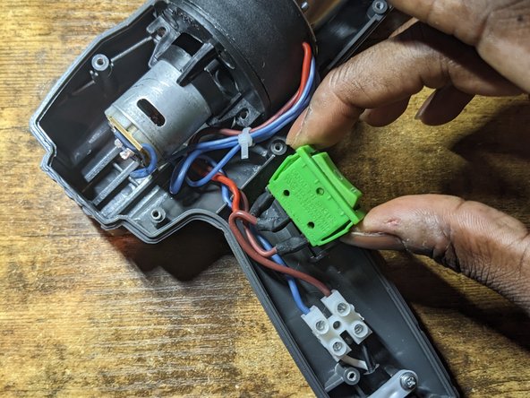
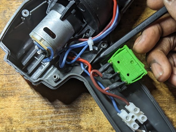
- Lift switch out of the bottom case.
- Lift wires out of their retaining slots.
- Seperate the fan unit from the plastic housing that is attached to the metal shield.
- Position fan and metal shield so that you can comfortably work on the circuit board located on the top of the motor.
- Method 1 (1 soldering irons)
- Add fresh solder to both ends of the diode and quickly move the soldering iron back and forth between both ends of the diode until the diode is released from the pads.
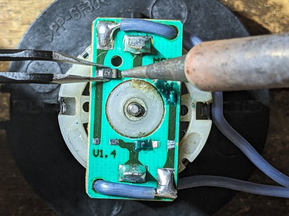
- Method 2 (2 soldering irons) [Photo 2]
- Heat up both soldering irons.
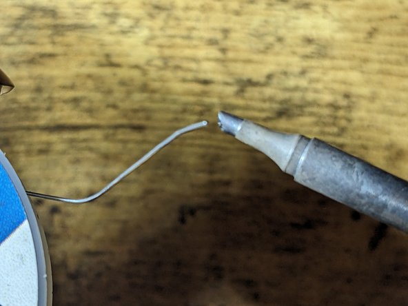
- Add fresh solder to both ends of the diode. (Photo 1)
- Hold iron onto the end of the diode and feed solder onto the board right at the tip of the soldering iron.
- Hold soldering irons on both ends of the diode and lift the diode off of the circuit board once the solder melts. (Photo 2)
- Repeat the above steps for the remaining diodes.
- Remove excess solder from pads. (Link to desoldering video and the importance of flux)
- Add flux to the pads
- Apply flux to desoldering wick braid
- Place desoldering wick braid on top of the pad
- Press the iron on the braid until the solder on the board wicks into the braid.
- Repeat above steps for the remaining pads.
- Add flux to pad. (Photo 1)
- Add small amount of solder to the tip of the iron. (Photo 2)
- Use tweezers to hold the diode centered in between both pads. (Photo 3)
- Touch the iron to the pad to tack the diode into position
- Add flux to second pad. (Photo 1)
- Hold iron onto the second end of the diode and feed solder onto the board right at the tip of the soldering iron. (Photo 2)
- Revisit the first end of the diode and repeat the step above to ensure a sufficient amount of flux is on the pad. (Photo 3)
- Use isopropyl alcohol on a q-tip to clean any excess flux left on the board.
- Repeat steps 7 and 8 for the remaining diodes.
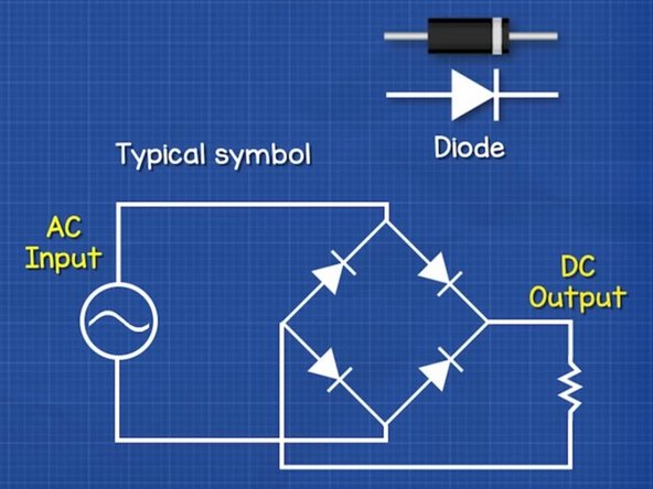
- Makes sure the diodes are arranged correctly, in order for the AC input to be rectified into a DC output.
- Take note of the end of the diode with a line through it.