Canon EOS Rebel T2i LCD Screen Assembly Replacement
ID: 180575
Description: This guide will show you how to disassemble the...
Steps:
- Before beginning, ensure that the camera is off, and the battery is removed.
- Pry open the rubber I/F terminal cap with your finger.
- Remove the two M1.7x2.5mm JIS #000 screws that are underneath the I/F terminal cap.
- Using a plastic pick, or another thin plastic prying tool, pop off the I/F terminal cover from the camera.
- On the left side of the camera, remove the following screw:
- One M1.7x6.0mm JIS #000 screw
- On the right side, remove the following screws:
- One M1.7x5.5mm JIS #000 screw
- One M1.7x3.5mm JIS #000 screw
- Remove the battery door.
- Open the battery door to about a 35° angle.
- Pull the battery door straight outwards.
- Remove the following screws from the bottom of the camera:
- One M1.7x6.0mm JIS #000 screw
- Two M1.7x2.5mm JIS #000 screws
- One M1.7x5.5mm JIS #000 screw
- Slide the viewfinder eyepiece vertically upwards.
- Start to pull the back cover partially off of the camera.
- Use caution when removing the back cover, there is a ribbon cable that connects the LCD screen to the main PCB board.
- Disconnect the LCD screen ribbon cable from the main PCB board.
- Use a plastic spudger to lift up the black locking tab.
- Carefully pull out the ribbon cable from its connector using a pair of angled tweezers.
- Finish pulling the back cover off of the camera body.
- Use extreme care while handling ribbon cables and connectors as they can be easy to damage.
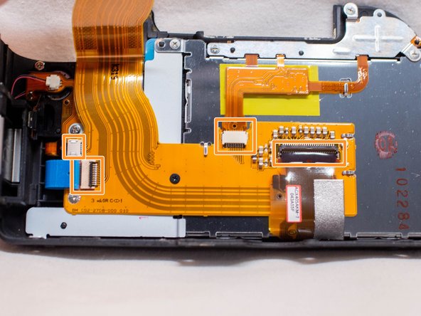
- Use a plastic spudger to lift up the locking tabs on the two ribbon cable connectors.
- iFixit connector guide
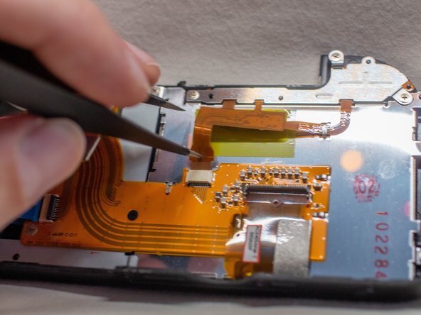
- Remove the four ribbon cables connected to the FPC assembly.
- Stick one of the ends of a pair of pointed tweezers through the hole in the ribbon cable and carefully pull the ribbon cable out of each connector.
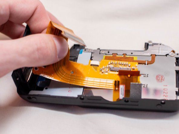
- Remove the following screws from the back cover FPC assembly:
- One M1.7x3.5mm JIS #000 screw
- One M1.7x4.0mm JIS #000 screw
- Carefully slide out the back cover FPC assembly from underneath the metal tabs holding it in place.
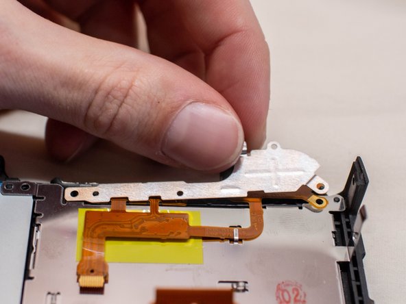
- Remove the following screws on the LCD screen assembly:
- Five M1.7x3.5mm JIS #000 screws
- Pull off the metal holding plate.
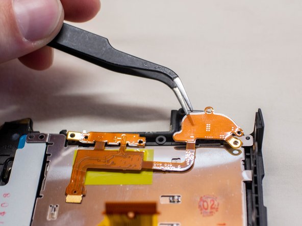
- With a pair of angled tweezers, carefully pull off the DOS FPC assembly.
- Gently lift up the right side of the LCD screen and pull it off of the back cover.
- Before installing a new LCD screen, ensure that there is no dust on the inside of the LCD window.