Canon EOS Rebel T3 Shutter Assembly Replacement
ID: 180760
Description: This guide shows you how to replace the shutter...
Steps:
- Pry open the rubber I/F terminal cap with your finger.
- Remove the two M1.7x4.5mm JIS #000 screws that are underneath the I/F terminal cap.
- Using a plastic pick, or another thin plastic prying tool, pop off the I/F terminal cover from the camera.
- On the left side of the camera, remove the following screw:
- One M1.7x4.5mm JIS #000 screw
- On the right side, remove the following screws:
- One M1.7x5.5mm JIS #000 screw
- One M1.7x4.5mm JIS #000 screw
- Remove the battery door.
- Open the battery door to about a 35° angle.
- Pull the battery door straight outwards.
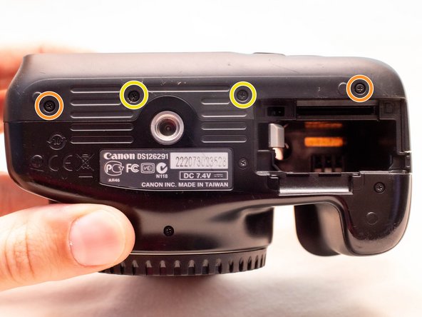
- Remove the following screws from the bottom of the camera:
- Two M1.7x4.5mm JIS #000 screws
- Two M1.7x3.0mm JIS #000 screws
- Carefully lift the back cover partially off of the camera.
- There are two ribbon cables still connecting the back cover to the camera.
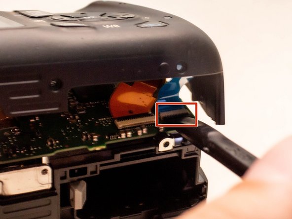
- Disconnect the right most ribbon cables from the main PCB board.
- Use a plastic spudger to lift up the black locking tab.
- Pull out the ribbon cable from its connector using a pair of angled tweezers.
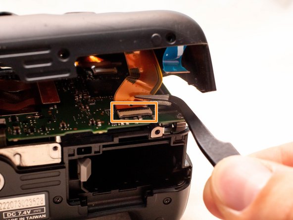
- With this ribbon cable disconnected, you will be able to move the back cover slightly farther away from the camera, giving you more room to remove the remaining ribbon cable.
- Remove the left ribbon cable using the same two steps as with the other ribbon cable.
- Remove the following screws on the front of the camera.
- Two M1.7x5.5mm JIS #000 screws
- On the bottom of the camera, remove the following screws:
- Two M1.7x5.5mm JIS #000 screws
- One M1.7x4.5mm JIS #000 screw
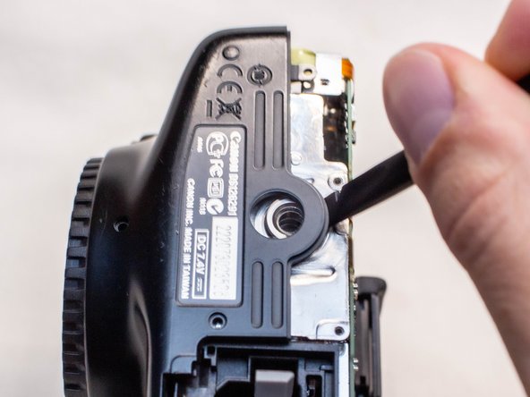
- Slide a spudger tool towards the tripod mount, underneath the plastic cover.
- Push the plastic cover up and over the tripod mount.
- Pull the front cover off of the camera.
- Electric Shock Warning: With the front cover off, the high voltage capacitor on the DC PCB board is now exposed. It is recommended that you use a capacitor discharge tool to ensure the capacitor is fully discharged before proceeding further.
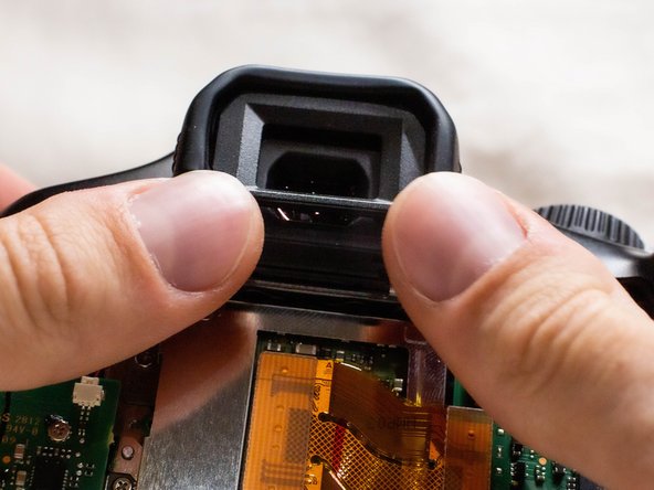
- Push up and slide off the eyepiece.
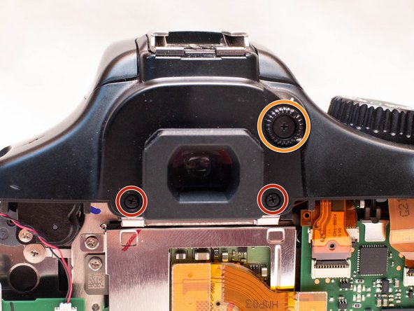
- Remove the following screws:
- Two M1.7x2.5mm JIS #000 screws
- One M1.7x3.6mm JIS #000 diopter screw
- Remove the following screws on the top of the camera:
- One M1.7x2.5mm JIS #000 screw
- One M1.7x5.5mm JIS #000 screw
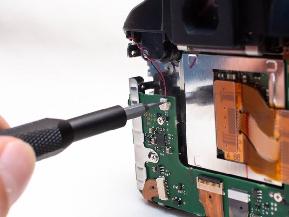
- Disconnect the microphone cable from the main PCB board.
- Position a flathead 2.5mm screwdriver between the main PCB board connector and the microphone connector.
- Gently wiggle the flathead screwdriver back and forth until the microphone connector comes free.
- If you do not have a flathead 2.5mm screwdriver, another similarly sized flathead screwdriver should work.
- Locate the mode dial ribbon cable on the main PCB board.
- Use a plastic spudger tool to carefully lift up the locking tab.
- Use caution when handling ribbon connectors and their connectors.
- Use a pair of angled tweezers to pull the ribbon cable out of the connector.
- Gently lift up the top cover.
- There are still several cables connecting the top cover to the camera. Be careful to not pull on these cables while lifting up the top cover.
- Set the top cover down, making sure not to pull on the cables still attached.
- Use caution while handling ribbon cables and ribbon cables connects to avoid damaging them.
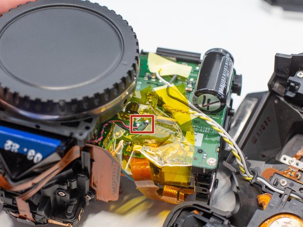
- Locate the two ribbon cables on the main PCB board which are marked in the picture.
- Disconnect the ribbon cables.
- These ribbon cables features a hole in them which can assist with disconnecting them. Use either a pair of tweezers or another tool with a thin point to pull out the ribbon cables utilizing this hole.
- Use a plastic spudger tool to carefully push up and disconnect the imaging sensor ribbon cable.
- Locate the remaining four ribbon cables connected to the main PCB board.
- Gently push up on the plastic lock tabs to unlock each of the ribbon cable connectors. Be especially careful with the wide lock tab, as it is particularly fragile.
- Disconnect each ribbon cable from the main PCB board.
- Use the same method from the previous step to remove these cables.
- Remove the following screws on the main PCB board:
- Three M1.7x2.5mm Phillips #000 screws
- Two M1.7x4.5mm Phillips #000 screws
- Slide off the metal I/F terminal shield.
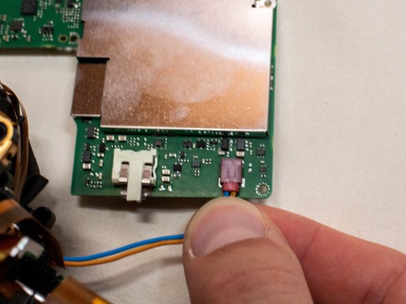
- Tilt the main PCB board upwards to reveal the remaining cable connection.
- Grab the two cables going into the connector, grabbing them as close to the connector as you can.
- Carefully pull the connector straight out.
- Using a plastic spudger tool, carefully push up and disconnect the ribbon cable from the image sensor.
- Remove the following screws from the image sensor:
- Two M1.7x1.6mm JIS #000 screws
- Three M1.7x5.5mm Phillips #000 screws
- Gently lift the image sensor straight up and away from the camera.
- Use extreme care while handling the image sensor, especially if you place on reinstalling the same image sensor back into the camera. The use of an anti-static wrist band is highly recommended. Avoid touching the front of the sensor with your fingers or any tools.
- When placing the image sensor down, place it with the sensor facing upwards. You may also want to place a container over the image sensor to prevent any dust from settling on it.
- If there is any dust or smudges on the sensor, you may consider performing a wet clean on the sensor while it is removed from the camera if you are planning on reinstalling it. Be sure to use a proper sensor cleaning kit and to follow their cleaning instructions.
- Under where the three M1.7x5.5mm Phillips #000 screws were, you will notice figure eight-shaped washers.
- Use a pair of tweezers to remove the washers.
- Caution: Keep very careful track of where each washer was removed from. Some washers may contain a stack of two washers. Each washer is a different thickness (down to 0.01mm) and reinstalling them in the wrong spot will result in out of focus images.
- You may want to use a digital caliper to measure each washer as you remove them, and record down the washer's thickness and which spot you removed it from.
- On the bottom of the camera, remove the following screws from the tripod socket plate:
- Two M2.0x3.5mm JIS #000 screws
- Two M2.0x5.0mm Phillips #000 screws
- Pull off the tripod socket plate.
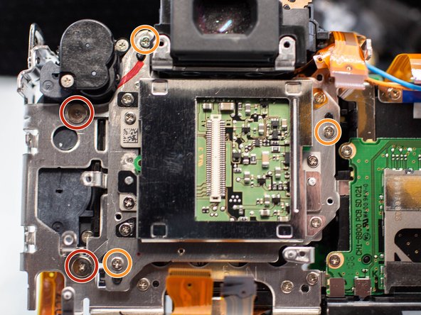
- On the back of the camera, remove the following screws holding the metal bracket in place:
- Four M1.7x5.5mm Phillips #000 screws
- Three M1.7x5.0mm Phillips #000 screws
- One M2.0x4.3mm JIS #000 screw
- Pull off the metal bracket, being careful not to damage any of the ribbon cables.
- Electric Shock Warning: If you have not already done so, use a capacitor discharge tool on the high voltage capacitor located on the DC PCB board before proceeding.
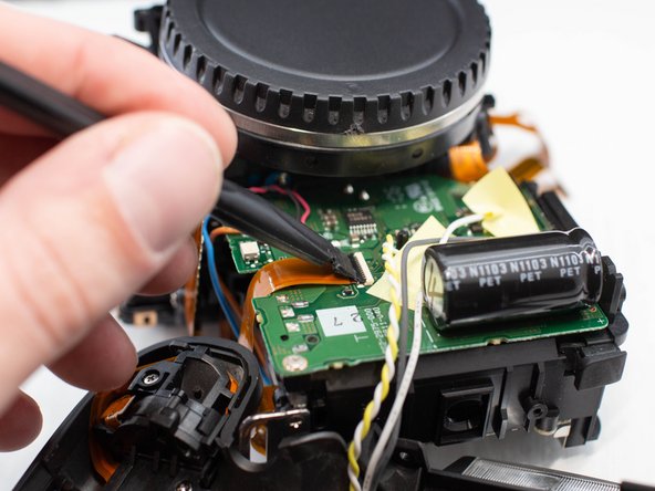
- On the DC PCB board, peel off the tape covering the shutter assembly power cable.
- Using a plastic spudger tool, lift up the black locking tab on the ribbon cable connector.
- Disconnect the ribbon cable and tuck the end of it away where it'll be safe while soldering.
- Place polyimide tape on the PCB board around the shutter assembly power cables. This is to help protect the components on the PCB board while desoldering the cables.
- Using a soldering iron and desoldering wick, desolder the two shutter assembly power cables from the DC PCB board. The wires should be red and black.
- iFixit desoldering guide
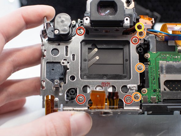
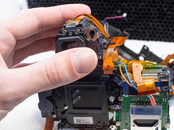
- On the top of the viewfinder, remove the following screws:
- Four M1.7x4.5mm Phillips #000 screws
- Lift the viewfinder assembly up and off of the camera.
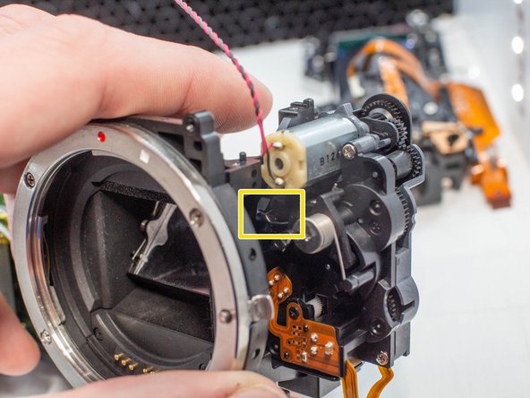
- On the shutter assembly, remove the following screws:
- One M1.7x4.5mm Phillips #000 screw
- One M1.7x7.0mm Phillips #000 screw
- Also remove the metal tab that is held on by the screw.
- Carefully lift off the shutter assembly.
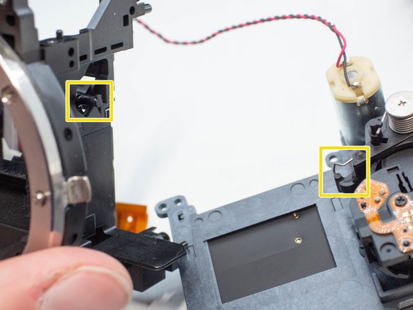
- When reinstalling the shutter assembly, make sure the metal spring gets hooked over the lever for the mirror.