iPhone 16 Microphone Removal
ID: 180973
Description:
Steps:
- Allow your phone's battery to drain below 25%, as a charged lithium-ion battery is a potential safety hazard.
- Unplug any cables from your phone.
- Hold the power and either volume buttons and slide to power off your phone.
- If your screen or back glass is badly cracked, lay overlapping strips of packing tape over the glass to protect yourself and make disassembly easier.
- Make sure there's a smooth area near the bottom edge that's big enough for a suction cup to stick to.
- Use a P2 pentalobe driver to remove the two 7.7 mm-long screws on either side of the charging port.
- If inserted too far, an opening pick can damage your device. Follow this step to mark your pick and prevent damage.
- Measure 3 mm from the tip and mark the opening pick with a permanent marker.
- You can also mark the other corners of the pick with different measurements.
- Alternatively, tape a coin to a pick 3 mm from the tip.
- Use a hair dryer or heat gun to heat the bottom edge of the back glass until it's hot to the touch.
- You can also use an iOpener to heat the back glass. Follow these instructions to heat and apply the iOpener properly.
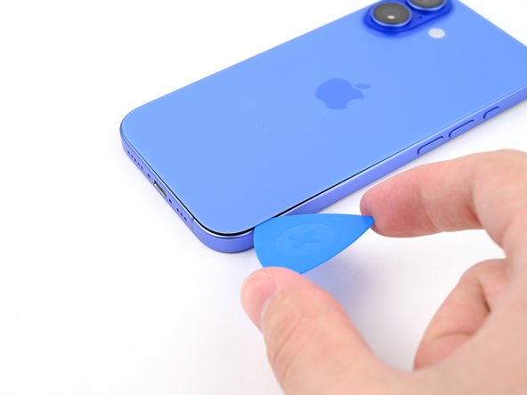
- Apply a suction handle to the bottom edge of the back glass.
- While supporting the frame with one hand, pull up on the handle with a strong, steady force to create a gap between the back glass and the frame.
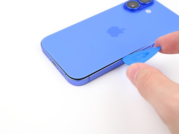
- Insert the tip of an opening pick into the gap.
- As you slice the adhesive securing the back glass in the following steps, don't insert your pick deeper than 3 mm to avoid damaging the following areas:
- A delicate cable connecting the back glass to the phone, right next to the volume down button. Don't insert your pick here to avoid slicing the cable.
- Multiple spring contacts around the perimeter of the phone.
- Use a hair dryer or heat gun to heat the right edge of the back glass until it's hot to the touch.
- Don't insert your pick deeper than 3 mm to avoid damaging the spring contacts.
- Slide your pick around the bottom right corner and to the volume down button to separate the adhesive and release the metal clip.
- Don't slide past the volume buttons to avoid damaging the wireless charging cable.
- You'll hear and feel the metal clip release as you pass it.
- Leave this pick inserted to prevent the adhesive from resealing.
- Use a hair dryer or heat gun to heat the left edge of the back glass until it's hot to the touch.
- Don't insert your pick deeper than 3 mm to avoid damaging the spring contacts.
- Insert a second opening pick at the bottom edge.
- Slide the second pick around the bottom left corner and along the left edge of the screen to separate the adhesive and release the metal clips.
- You'll hear and feel the metal clips release as you pass them.
- Leave this pick inserted at the top left corner to prevent the adhesive from resealing.
- Use a hair dryer or heat gun to heat the top edge of the back glass until it's hot to the touch.
- Don't insert your pick deeper than 3 mm to avoid damaging the spring contacts.
- Slide your second opening pick around the top left corner and along the top edge to separate the adhesive and release the metal clips.
- You'll hear and feel the metal clips release as you pass them.
- Continue sliding your pick around the top right corner until you reach the Action button.
- Leave this pick inserted to prevent the adhesive from resealing.
- At this point, the back glass should be free from the frame. If the back glass feels stuck, go back around the perimeter with your pick to check for missed sections of adhesive or stuck clips.
- Swing open the back glass to the right of the phone to separate the remaining adhesive.
- Support the back glass with a clean, sturdy object.
- Remove the opening picks before continuing.
- Use a tri-point Y000 driver to remove the two 1 mm‑long screws securing the middle connector cover.
- Insert the point of a spudger in either cutout on the middle connector cover.
- Slide the cover towards the left edge of the phone and release its hook from its slot on the logic board.
- Remove the cover.
- Use the point of a spudger to pry up and disconnect the battery press connector.
- Use the point of a spudger to pry up and disconnect the wireless charging coil press connector.
- Lift the back glass off the frame and remove it.
- Use a Phillips screwdriver to remove the two 1.8 mm‑long screws securing the Taptic Engine bracket.
- Use tweezers, or your fingers, to remove the Taptic Engine bracket.
- Use the point of a spudger to pry up and disconnect the Taptic Engine press connector.
- Use a Phillips screwdriver to remove the two screws securing the Taptic Engine:
- One 2.2 mm‑long screw
- One 1.7 mm‑long screw
- Use the point of a spudger to lift the Taptic Engine out of the frame.
- Remove the Taptic Engine.
- Remove the five screws securing the loudspeaker:
- Two 1.5 mm‑long Phillips screws
- One 2.0 mm‑long Phillips screw
- One 2.9 mm‑long Phillips screw
- One 1.2 mm‑long tri‑point Y000 screw
- Use the point of a spudger to lift the loudspeaker out of the frame.
- Remove the loudspeaker.
- Use the tip of a spudger to disconnect the microphone press connector.
- Remove the four screws securing the microphone:
- Two 3.3 mm‑long standoff screws
- One 1.1 mm‑long tri‑point Y000 screw
- One 1.5 mm‑long Phillips screw
- If you don't have a standoff driver, you may use a thin flathead driver—but be careful not to strip the shallow notches in the screw heads.
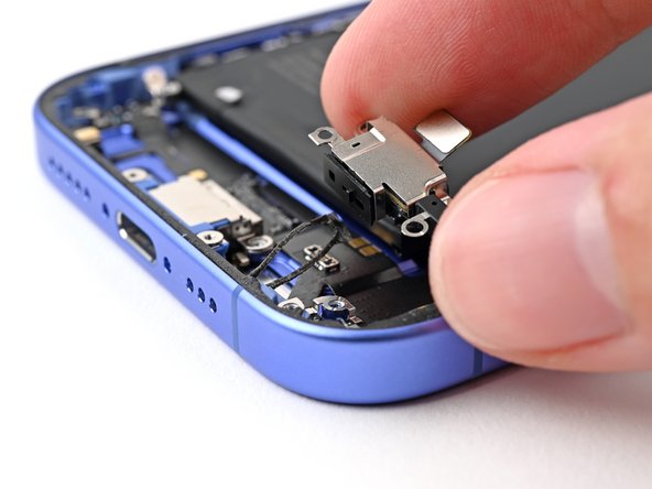
- Use the flat end of a spudger to lift the microphone enough to grip it with your fingers.
- Pull the microphone away from the frame to separate the adhesive.
- Remove the microphone.