Canon EOS Rebel T7i Strap Holder Replacement
ID: 181035
Description: This guide will show you how to replace the two...
Steps:
- Before beginning, remove the battery and SD card from the camera.
- Using your thumbs, push up on the eyepiece to remove it.
- Remove the battery door.
- Open the battery door to about a 35° angle.
- Pull the battery door straight outwards.
- Underneath the right I/F terminal cap, remove the following screws:
- Two M1.7x5.5mm JIS #000 screws
- On the right side of the camera, remove the following screws:
- Two M1.7x4.5mm JIS #000 screws
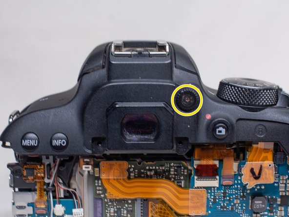
- On the back of the camera, remove the following screws next to the viewfinder:
- Two M1.7x5.0mm Phillips #000 screws
- On the bottom of the camera, remove the following screws:
- Four M1.7x5.0mm Phillips #000 screws
- Using a plastic opening pick, partially peel up the top of the back rubber grip.
- Carefully begin lifting the back cover up away from the camera body.
- Do not lift it all the way off. There is still a ribbon cable attaching the back cover to the main PCB board.
- Using a plastic spudger tool, gently pry off the back cover ribbon cable from the main PCB board.
- Underneath the left I/F terminal cap, remove the following screw:
- M1.7x5.5mm JIS #000 screw
- Using a plastic opening pick, peel off the front name plate.
- Underneath where the name plate was, remove the following screw:
- One M1.7x5.5mm Phillips #000 screw
- Pull off the I/F terminal cover.
- On the bottom of the camera, remove the following screws:
- Four M1.7x5.0mm Phillips #000 screws
- On the front of the camera, remove the following screws:
- Two M1.7x6.0mm JIS #000 screws
- On the right side of the camera, remove the following screws:
- Two M1.7x4.5mm JIS #000 screws
- Use a plastic spudger to pry up on the bottom of the front cover and lift it over the tripod socket.
- Pull the front cover off the camera body.
- Electric Shock Warning: With the front cover off, the high voltage capacitor on the DC PCB board is now exposed. It is recommended that you use a capacitor discharge tool to ensure the capacitor is fully discharged before proceeding further.
- Remove these two cables from the main PCB board using a plastic spudger tool.
- Remove the third cable using a pair of blunt tweezers.
- Place the end of the tweezers in the small notch in the cable connector and push the connector out.
- Using a pair of blunt tweezers, carefully pull out the red and yellow cables from the DC PCB board.
- Remove the following screws from the top of the camera:
- One M1.7x3.0mm JIS #000 screw
- One M1.7x5.5mm JIS #000 screw
- On the back of the camera, remove the diopter adjusting dial.
- Using a pair of tweezers, move the two cables on the left side of the main PCB board so that they won't get caught while removing the top cover.
- You may find it easier to remove the speaker cable (with the black and red wires) first so that it's out of your way.
- Carefully lift up the top cover off the camera body. Be careful that no cables get caught while lifting it off.
- Remove the followings screws from the right strap holder:
- Two M2.0x5.0mm Phillips #000 screws
- Remove the followings screws from the left strap holder:
- Two M2.0x5.0mm Phillips #000 screws