iPhone 16 Pro Logic Board Installation
ID: 181160
Description: Reassembly steps to install the logic board in...
Steps:
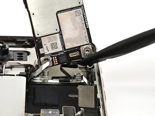
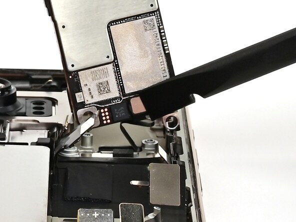
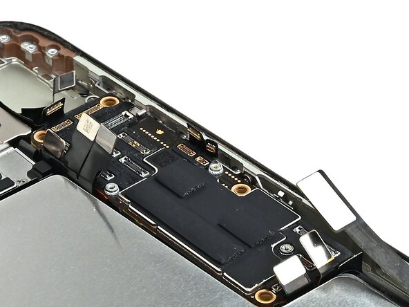
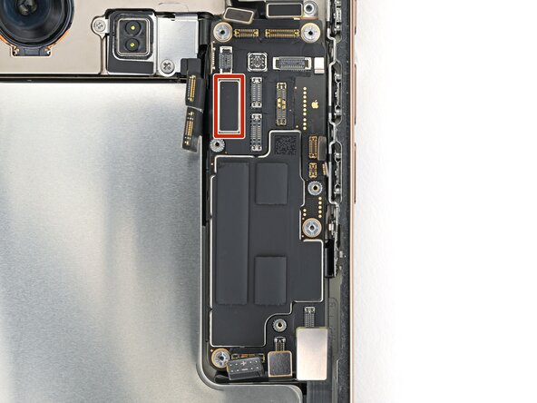
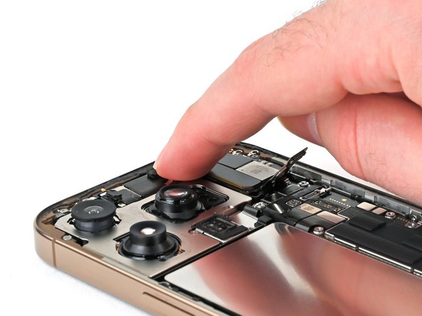
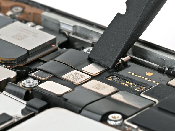
- Hold the logic board above the phone so the socket on the underside of the board is close to the front sensor cable.
- Use your finger or a spudger to press the front sensor cable connector into its socket on the logic board until it clicks into place. Don't try to force the connector into place. If you're having trouble, reposition it and try again.
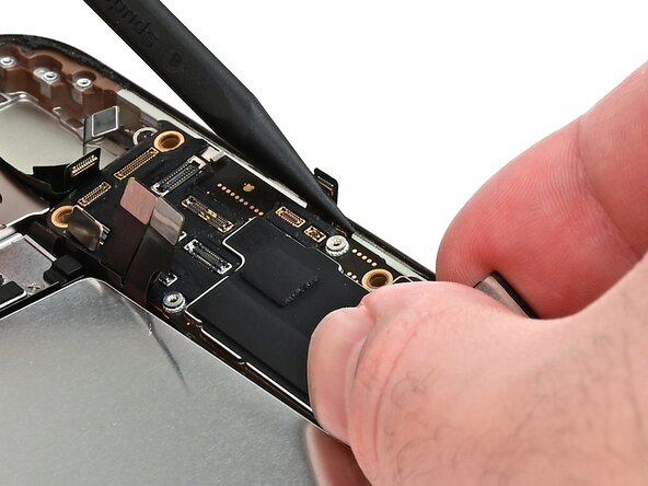
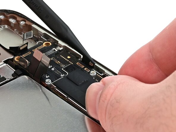
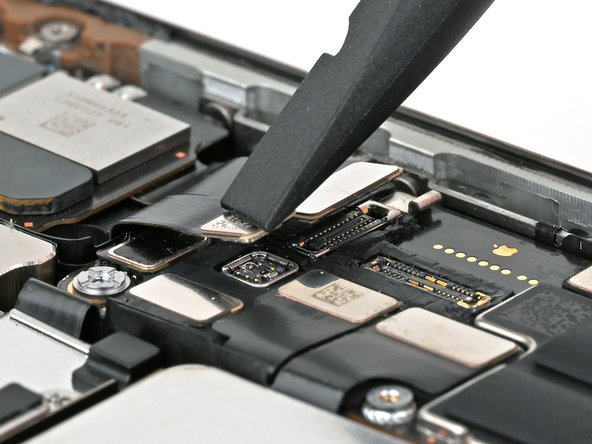
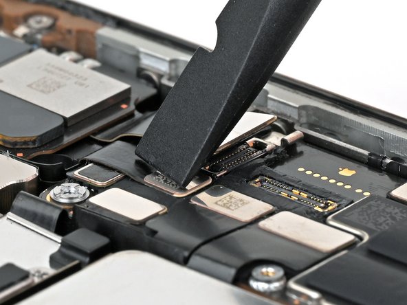
- Use your fingers or a spudger to gently hold all the loose press connectors out of the way so you can lay the logic board in place.
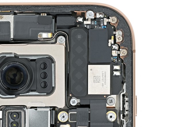
- Lay the logic board in its recess.
- You can't directly connect the display connector to the bottom of the logic board without removing the screen, but you might successfully connect it by screwing the logic board in place. Be sure to test your iPhone later in this guide.
- If it fails, work back to this step and try again or follow the screen replacement guide to connect it manually.
- Make sure the logic board rests in place against its screw posts. The posts will properly align the board to the display connector underneath it.
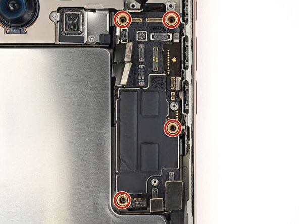
- Use a standoff screwdriver to install the four screws securing the logic board:
- Two 4.5 mm‑long screws
- One 3.4 mm‑long screw
- One 4.2 mm‑long screw
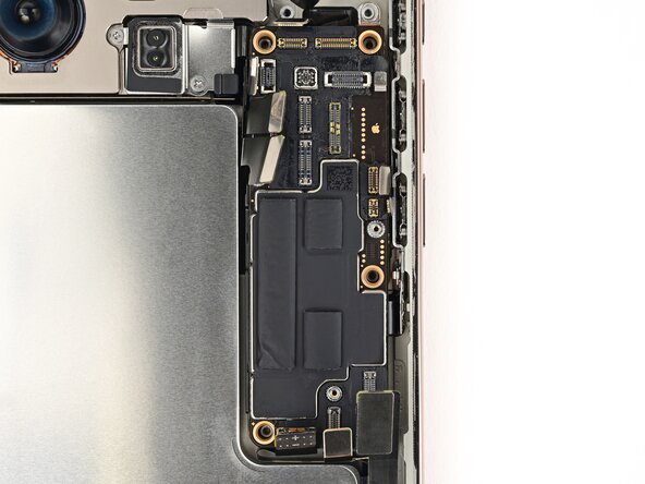
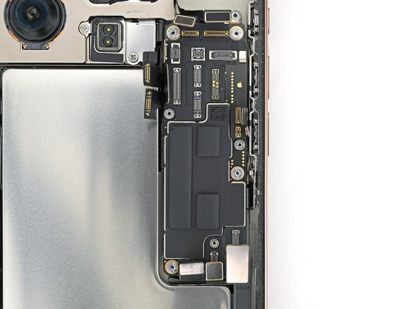
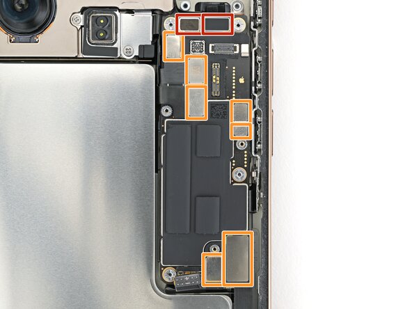
- To connect press connectors like these, carefully align and press down on one side until it clicks into place, then repeat on the other side. Don't press down in the middle. If the connector is misaligned, the pins can bend, causing permanent damage.
- Use your finger or a spudger to connect the press connectors to the top of the logic board:
- Three black connectors
- One of the black connectors is under the two silver connectors on the left edge of the board, and needs to be connected first.
- Seven silver connectors
- Don't connect the battery press connector, labeled with a "+" and "-".
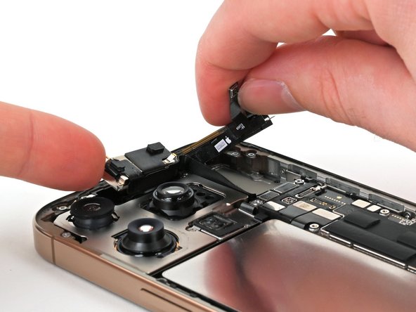
- Insert the top edge of the earpiece speaker into its cutout at a downward angle before pressing it flat to the frame.
- You may have to lift the front camera assembly just enough to get the earpiece speaker in its cutout. Route the antenna and earpiece speaker cables to the right of the front camera cables. Press the front camera into its cutout, then push its cables flush with the rear cameras.
- Use a Phillips screwdriver to install the six screws securing the earpiece speaker:
- Three 1.2 mm‑long screws
- Two 1.8 mm‑long screws
- One 1.7 mm‑long screw
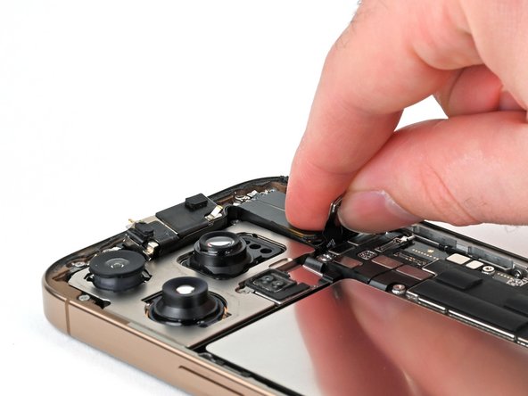
- Use your finger or a spudger to connect the earpiece speaker and 5G mmWave antenna (US only) press connectors, located on the top right corner of the logic board.