iPhone 16 Pro Taptic Engine Removal
ID: 181298
Description: Prerequisite guide to remove the Taptic Engine...
Steps:
- Allow the phone's battery to drain below 25%, as a charged lithium-ion battery is a potential safety hazard.
- Unplug any cables from the phone.
- Hold the power and either volume buttons and slide to power off the phone.
- If the screen or back glass is badly cracked, lay overlapping strips of packing tape over the glass to protect yourself and make disassembly easier.
- Make sure there's a smooth area near the bottom edge that's big enough for a suction cup to stick to.
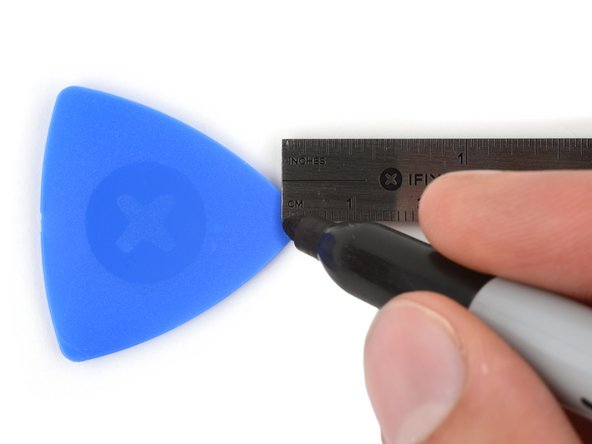
- If inserted too far, an opening pick can damage your device. Follow this step to mark your pick and prevent damage.
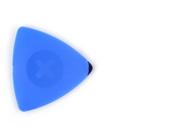
- Measure 3 mm from the tip and mark the opening pick with a permanent marker.
- You can also mark the other corners of the pick with different measurements.
- Alternatively, tape a coin to a pick 3 mm from the tip.
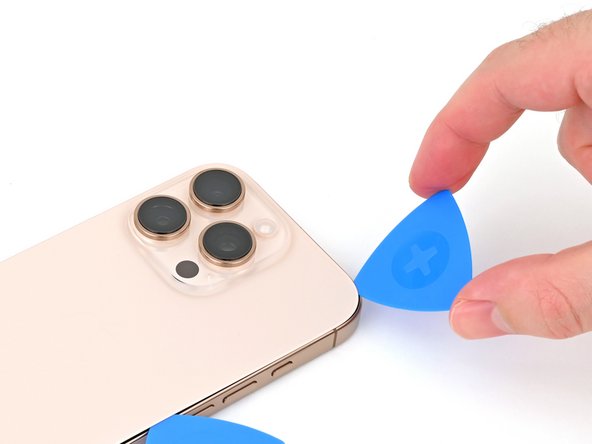
- Use a P2 pentalobe screwdriver to remove the two 7.4 mm‑long screws on either side of the USB-C port.
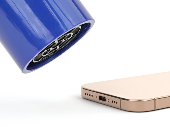
- Apply a heated iOpener to the bottom edge of the back glass for two minutes.
- Alternatively, you can use a hair dryer or heat gun to heat the bottom edge of the back glass until it's hot to the touch.
- Be careful not to heat the phone hotter than this—the battery is susceptible to heat damage.
- Apply a suction handle to the bottom edge of the back glass, above the USB-C port.
- Pull up on the handle with a strong, steady force to create a gap between the back glass and the frame.
- Insert the tip of an opening pick into the gap.
- As you slice the adhesive securing the back glass in the next steps, be careful of the following areas:
- There's a delicate cable connecting the back glass to the phone, right next to the volume up button. Don't insert your pick here to avoid slicing the cable.
- There are multiple spring contacts around the perimeter of the phone. Be extra careful not to insert your pick deeper than suggested in each step to avoid bending these contacts.
- If you damage the spring contacts, gently bend them back with a spudger or opening pick so they align with their gold contact pads on the back glass.
- Don't insert your pick deeper than 5 mm on the bottom edge to avoid damaging the spring contact.
- Slide your pick back and forth along the bottom edge to separate the adhesive.
- Leave your pick inserted in the bottom right corner to prevent the adhesive from resealing.
- Heat the right edge of the back glass until it's hot to the touch.
- Slide your pick around the bottom right corner and halfway up the right edge, or until you feel a hard stop at a clip securing the back glass.
- Don't slice near the volume buttons to avoid damaging the wireless charging/flash cable.
- Leave this pick inserted to prevent the adhesive from resealing.
- Heat the left edge of the back glass until it's hot to the touch.
- Insert a second opening pick at the bottom edge.
- Slide the second pick around the bottom left corner and along the left edge of the screen to separate the adhesive and release the metal clips.
- You'll hear and feel the metal clips release as you pass them.
- Leave this pick inserted at the top left corner to prevent the adhesive from resealing.
- Heat the top edge of the back glass, including the area around the volume buttons, until it's hot to the touch.
- Don't insert your pick deeper than 3 mm along the top edge to avoid damaging the spring contacts.
- Slide your opening pick across the top edge and around the top right corner to the volume up button to separate the adhesive.
- You'll hear and feel clicks as the top two clips release.
- Don't try to fully remove the back glass just yet—it's still attached with a delicate ribbon cable. Follow the next few steps to remove it safely.
- If the back glass doesn't swing open easily, don't force it—go back around the perimeter with your pick to check for missed sections of adhesive or stuck clips.
- You may need to lift the back glass up slightly before swinging it open to fully disengage the clips.
- Gently swing open the back glass towards the volume buttons.
- Support the back glass with a clean, sturdy object like a small box to avoid straining the cable.
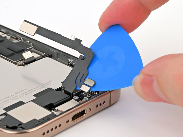
- Remove the opening picks.
- Consider using polyimide tape to protect the rear camera lenses while you're working inside the phone. Don't push against the lenses to avoid damaging the delicate stabilizers.
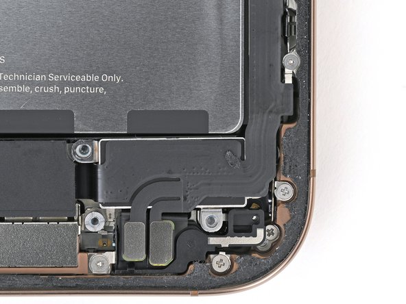
- Use a tri-point Y000 screwdriver to remove the three screws securing the lower connector cover:
- Two 1.2 mm‑long screws
- One 1.0 mm‑long screw
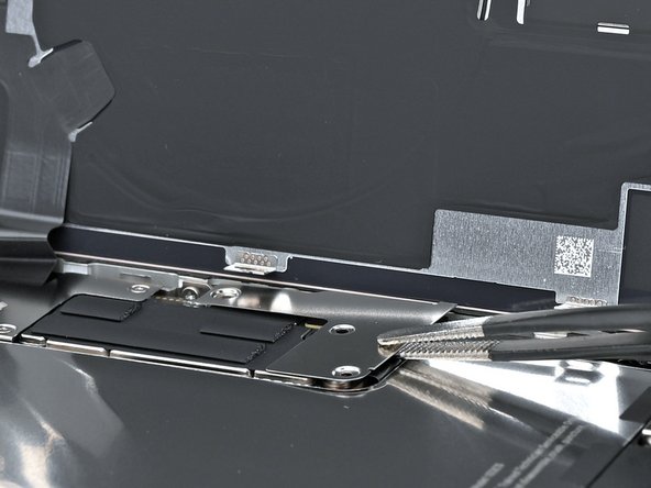
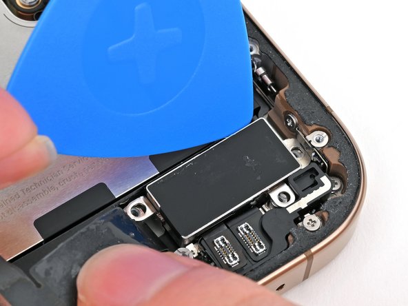
- Use tweezers or your fingers to pick up and remove the lower connector cover.
- Use the point of a spudger to pry up and disconnect the battery press connector.
- Use a tri-point Y000 screwdriver to remove the four screws securing the upper connector cover:
- Two 1.0 mm‑long screws
- One 1.2 mm‑long screw
- One 1.6 mm‑long screw
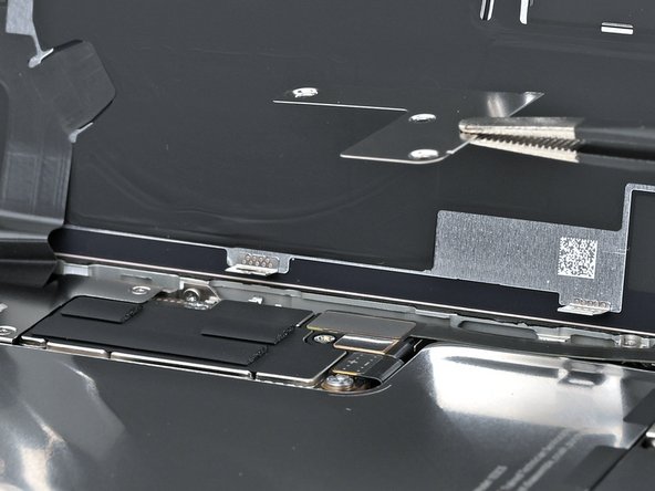
- Use tweezers or your fingers to pick up and remove the upper connector cover.
- Use the point of a spudger to pry up and disconnect the back glass press connector.
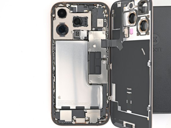
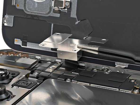
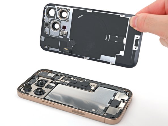
- Lift the back glass off the frame and remove it.
- Use a Phillips screwdriver to remove the three screws securing the Taptic Engine cover:
- One 3.0 mm‑long screw
- Two 1.7 mm‑long screws
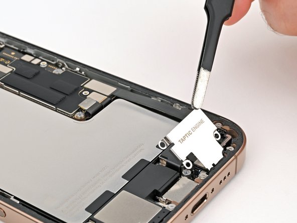
- Use tweezers or your fingers to lift the top edge of the Taptic Engine cover.
- Once the bottom edge unlatches from the frame, remove the Taptic Engine cover.
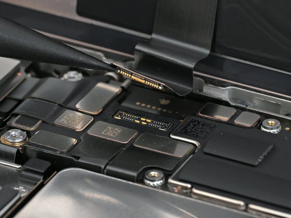
- Use the point of a spudger to pry up and disconnect the lower assembly cable press connector from the logic board.
- Use the point of a spudger to pry up and disconnect the two press connectors near the bottom right edge of the frame.
- Use a tri-point Y000 screwdriver to remove the 1.0 mm‑long screw securing the lower assembly cable.
- Use an iOpener or hair dryer to heat up the lower assembly cable section on top of the Taptic Engine until it's hot to the touch.
- Slide an opening pick under the lower assembly cable to separate it from the Taptic Engine.
- Carefully bend the cable out of the way so you can access the Taptic Engine.
- Use a Phillips screwdriver to remove the 1.9 mm‑long screw securing the Taptic Engine.
- Slide the tip of an opening pick along the top edge of the Taptic Engine to separate the plastic buffer strip adhered to it.
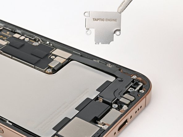
- Use the point of a spudger to pry up the Taptic Engine from its top-right corner.
- Be careful not to pry against the battery.
- Remove the Taptic Engine.