Ortizan X10 Motherboard Replacement
ID: 186067
Description: The Ortizan X10 is a portable Bluetooth speaker...
Steps:
- Use an opening tool to remove the rubber end caps.
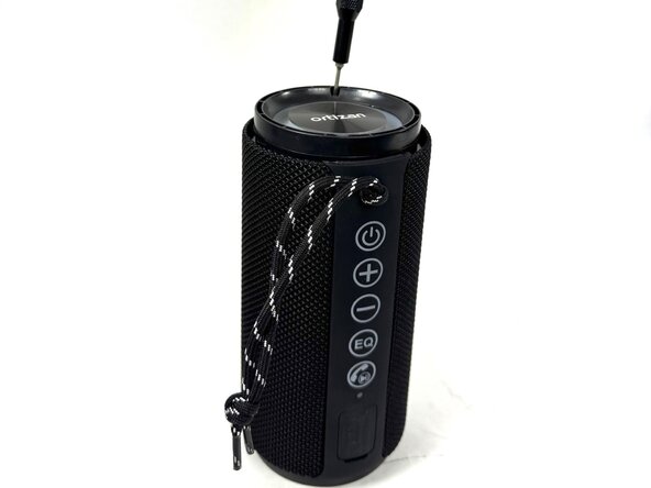
- Use a Phillips screwdriver to remove the four screws (two on each end).
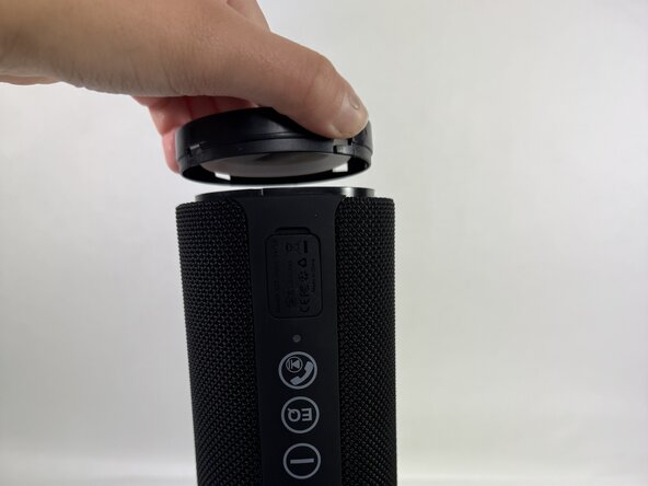
- Firmly grip the top of the speaker, stabilize the base, and twist the cap counterclockwise to loosen and remove. Repeat this step for the bottom cap.
- Insert an opening tool into the seam between the grille and body. Lift and crack it open just a little.
- Using your hands, pull the speaker out of the casing by holding the speaker in one hand and the shell in the other.
- Utilizing the iFixit Mahi 1/4" bit driver with the Philips #00 Bit, remove the screw securing the LED circuit board. Apply firm, even pressure while turning the screwdriver counterclockwise (to the left) to loosen and remove the screw.
- Gently peel away the rubber button strip from the device housing. Use the iFixit opening tool to lift one end of the rubber strip, then use your hands to peel off the rest.
- Utilizing the iFixit Mahi 1/4" bit driver with the Philips #00 Bit, remove the eight screws surrounding the button interface to detach the plastic button housing.
- To remove the eight screws, align the tip of the screwdriver (with the bit already inserted) with the head of the screw, making sure it fits snugly into the grooves. Apply firm, even pressure while turning the screwdriver counterclockwise (to the left) to loosen and remove the screw.
- Utilize the iFixit Opening Tool to lift and remove the rubber power button board.
- Carefully extract the motherboard from the device by gently shifting it left and right to disengage it from internal casing.
- Be cautious when removing the motherboard, as JST Connectors are attached to it and can be damaged if pulled or disconnected improperly.
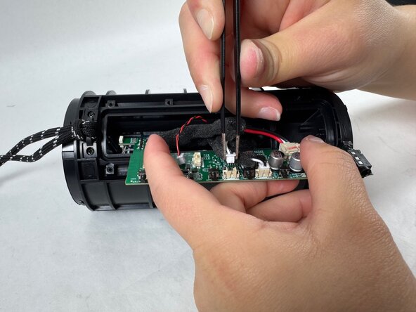
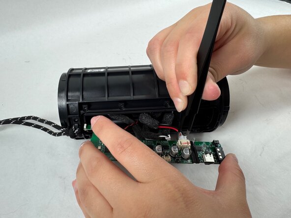
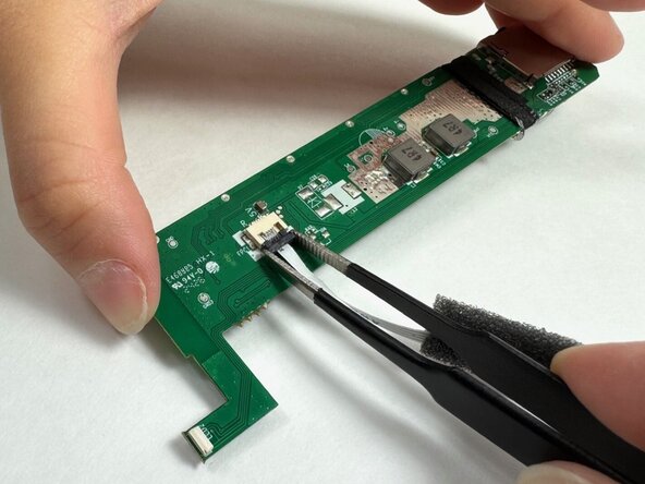
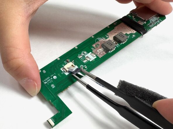
- Utilizing the Precision Tweezer disconnect all three JST Connectors connected to the motherboard.
- To disconnect the first three JST Connectors, use the precision tweezer and firmly grip the sides of the connectors and pull it up.
- To disconnect the last JST Connector, use the precision tweezer, firmly grip the sides of the connectors and carefully move it side to side until it unplugs.
- For helpful instructions on disconnecting various connector types, refer to this guide.
- To disconnect the LED connector from the motherboard, use a pair of tweezers or a clean fingernail to gently wiggle the black connector from side to side until it slides off.
- Use caution when wiggling this connector side to side, as excessive force may cause it to break.
- Once the connector is removed, the white ZIF tape will naturally detach from the motherboard. At this point, all components have been successfully disconnected, and the motherboard is ready for replacement. To reassemble your device, follow these instructions in reverse order.