Sonos Era 100 Power Socket Replacement
ID: 186130
Description: Is your Sonos Era 100 not playing any sound or...
Steps:
- Gently pull off the rubber foot on the the bottom of the speaker.
- Take care not to stretch or damage the rubber foot if you intend to reuse it. Use a hairdryer or iOpener to lightly heat the foot adhesive to aid in removal.
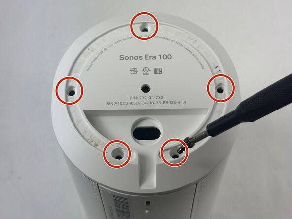
- Remove the five 11 mm Torx T20 screws that secure the bottom plate.
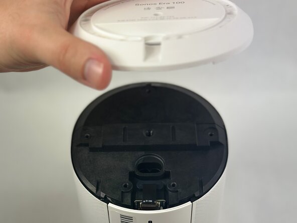
- Carefully lift off the bottom plate.
- Carefully disconnect the ribbon cable connected underneath the bottom panel.
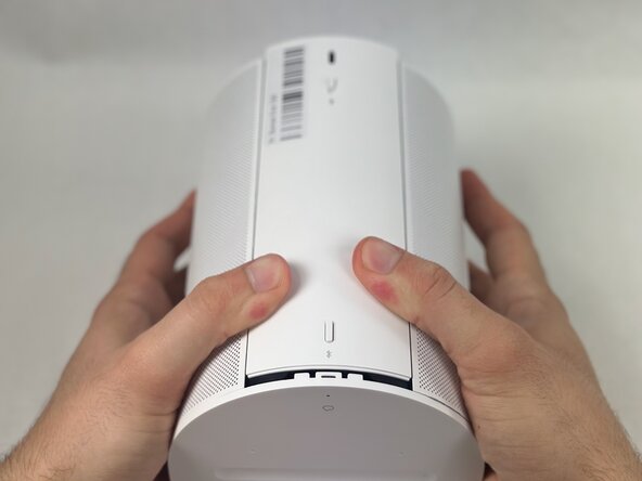
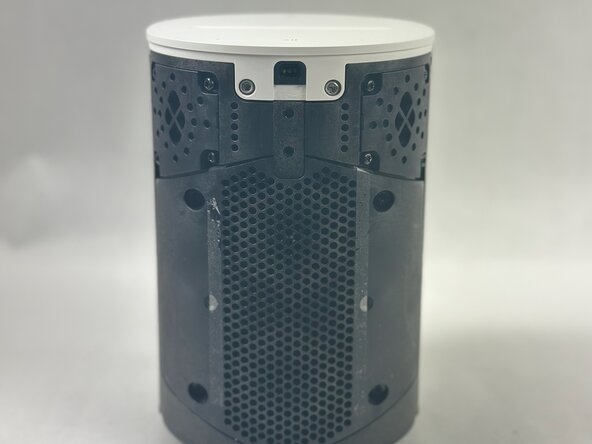
- To detach the back panel, gently push it in a downward motion.
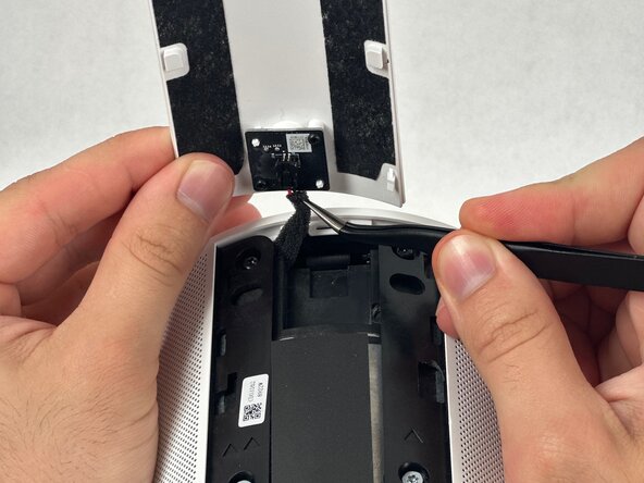
- Be especially mindful of the delicate ribbon cable attached to the top edge.
- Use tweezers to disconnect the USB-C PCB from the back panel.
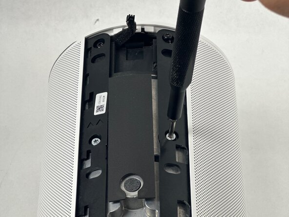
- Remove the 8 mm and 11 mm T10 Torx screws securing the speaker grille.
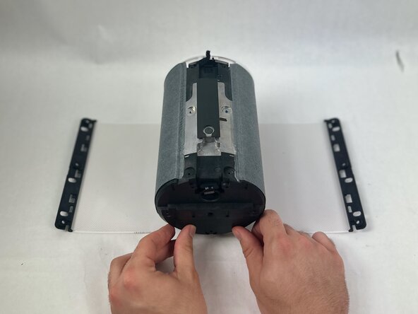
- Once removed, the speaker grill should fall to both sides of the speaker.
- Using a halberd spudger, carefully remove the foam tape. Do this by keeping tension on the foam shown in the images and slicing underneath the tape.
- Pull the speaker grille off.
- Remove all four T10 Torx screws securing the touch bar assembly.
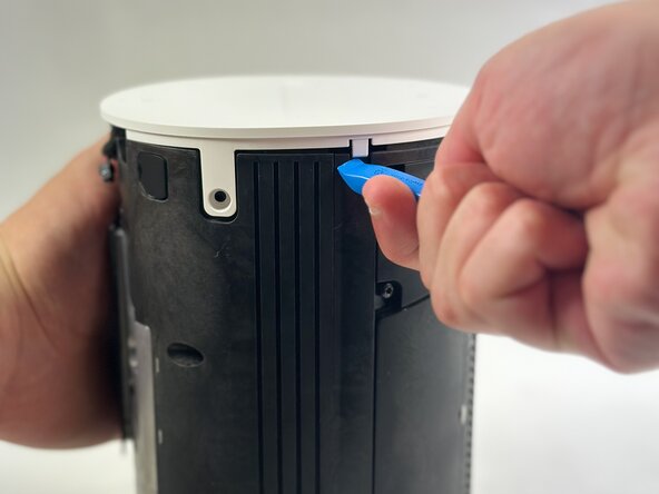
- Use an opening tool to release all four white retaining clips.
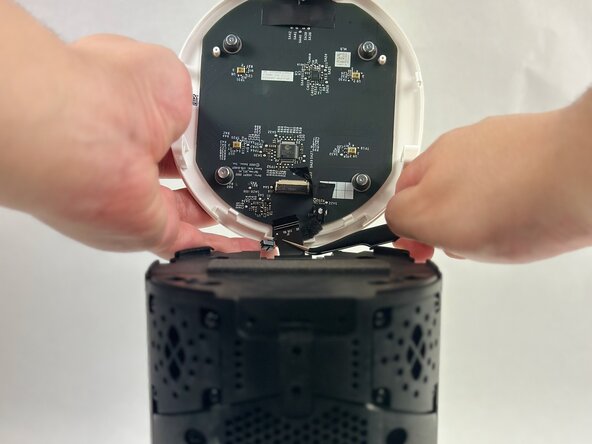
- Lift the touch bar assembly perpendicular to the unit, with care not to strain the connected ribbon cable.
- Lift the black ZIF locking flap that secures the touch bar assembly ribbon cable.
- Disconnect the ribbon cable.
- Remove the touch bar assembly.
- Remover rubber plugs with a metal spudger
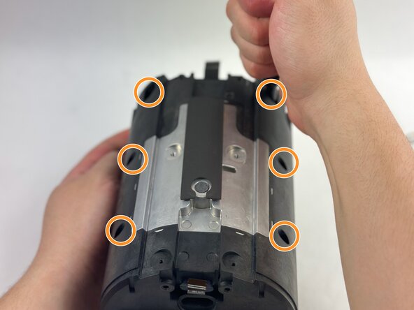
- Remove front-bottom two T10 Torx 11 mm screws.
- Remove the six front T10 Torx screws.
- Remove the four T10 Torx screws on the back of the device.
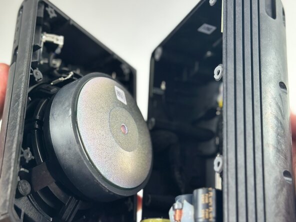
- Pry open the speaker body to access the internals.
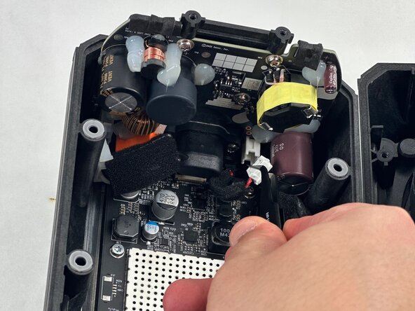
- Disconnect both of the power supply board connectors from the motherboard.
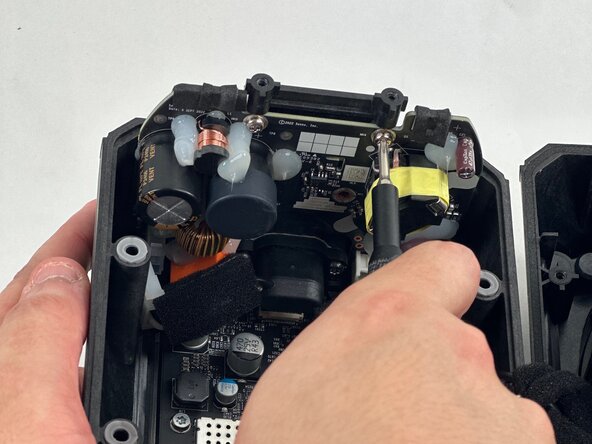
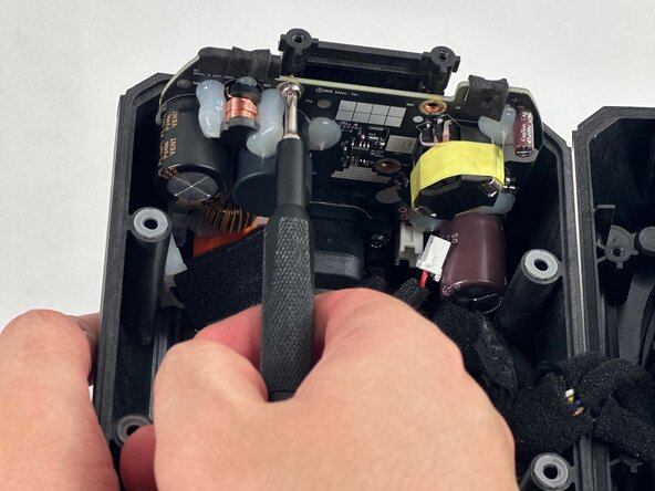
- Use a T10 Trox screwdriver to remove the three 8 mm screws securing the power supply board.
- Carefully remove the board.
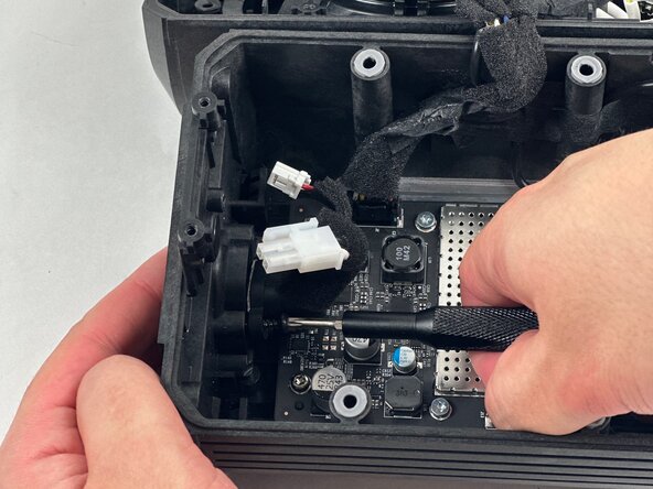
- Remove the two 11 mm T20 Torx screws securing the socket.
- Carefully remove the power socket.