HP Elitebook 840 G8 Display Panel Replacement
ID: 186245
Description: Use this guide to replace a display that is...
Steps:
- Before starting your repair, allow your laptop's battery to drain below 25%—a charged lithium-ion battery is a potential safety hazard if accidentally damaged.
- Save your work, fully shut down your laptop, and unplug all cables.
- Despite the standards, Phillips screwdrivers can vary in size and shape—two drivers labeled as the same size may fit differently in the same screw. Use the size that fits the most snug into the screw head to avoid stripping it.
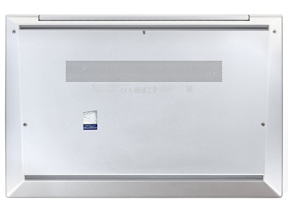
- Use a Phillips screwdriver to fully loosen (but not remove) the five captive screws securing the bottom cover.
- Position your laptop so the rear edge (with the screen hinge) is closest to you.
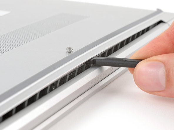
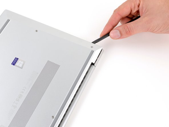
- Insert the flat end of a spudger between the rear edge of the bottom cover and the frame, near the middle screw and ELITEBOOK text.
- If you're having trouble inserting your spudger, make sure the screw is fully loosened. If necessary, use your fingers to gently pull the screw up.
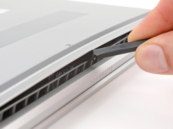
- Use your spudger to pry up the cover to release the clip securing it.
- Leave the spudger inserted under the bottom cover for the next step.
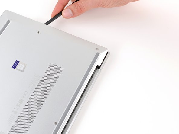
- Slide your spudger along the rear edge toward one of the corners to release the rear edge clips.
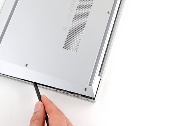
- Rotate your spudger around the corner and up the edge to release the clips securing the short edge of the cover.
- Reinsert the flat end of a spudger near the ELITEBOOK text.
- Repeat the previous step for the other side of the cover to release the remaining clips.
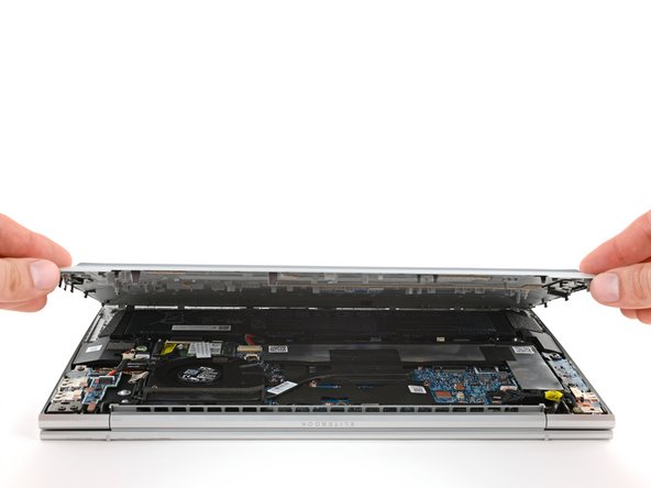
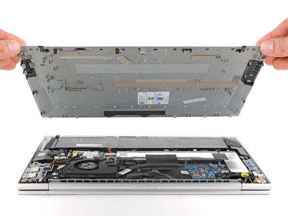
- Lift and remove the bottom cover.
- The cover should lift away easily. If you feel resistance, use the flat end of a spudger to release any remaining clips, and check that all screws are fully loosened.
- During reassembly, slide the clips along the front edge of the cover (opposite the hinge) into their slots on the frame, then lay the cover down. Press firmly around the perimeter to engage all of the clips.
- Position your laptop so the front edge (opposite the screen hinges) is closest to you.
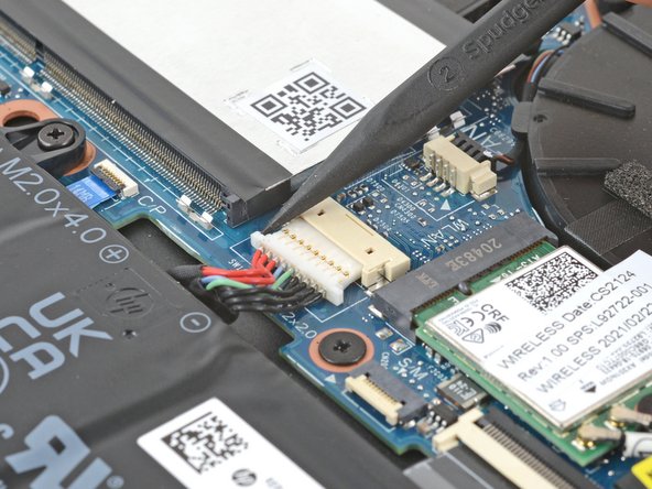
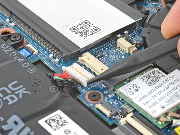
- Use the point of a spudger or your fingernail to push on alternating sides of the battery's sliding connector to walk it completely out of its socket.
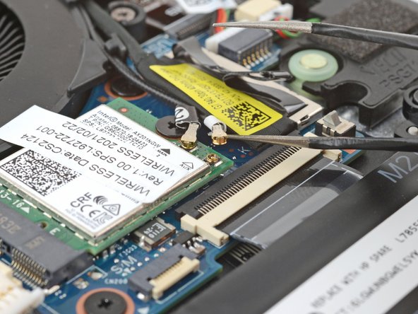
- Slide an arm of a pair of angled tweezers under the metal neck of one of the coaxial connectors on the WLAN (Wi-Fi) module, located just below the fan.
- Lift straight up to disconnect the cable.
- Repeat to disconnect the second connector.
- During reassembly:
- Connect the cable with black tape to the socket with a black arrow below it, and the cable with white tape to the socket with a white arrow.
- Use tweezers to hold a connector in place over its socket and gently press down with your finger or a spudger—the connector should "snap" into place. If you're having trouble, reposition the head and try again. Don't use excessive force.
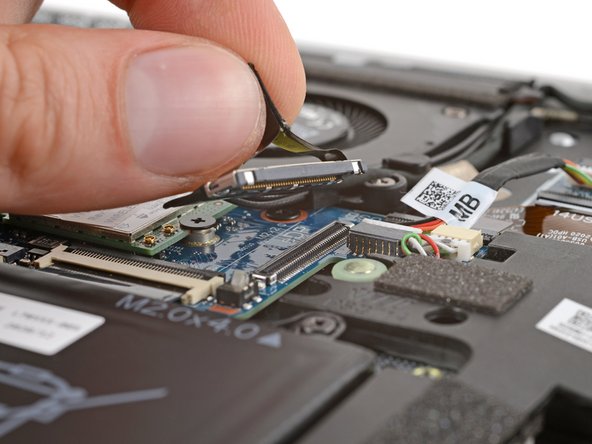
- Use your fingers to grip the plastic pull tab on the right display cable press connector, below the fan.
- Pull straight up to disconnect the connector.
- During reassembly, align the connector carefully over its socket and press down with your fingertip—first on one side, then the other—until it clicks into place. Don't try to force the connector into place. If you're having trouble, reposition it and try again. Don't use excessive force.
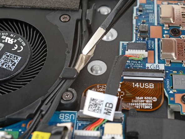
- Use tweezers or your fingers to peel up the cable tape near the right side of the fan.
- You don't need to fully remove the tape—it can stay on the cable.
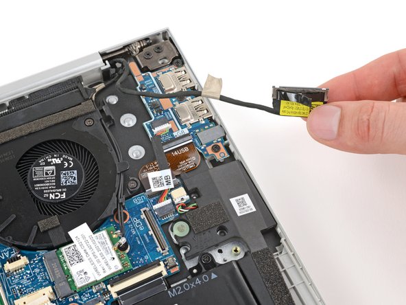
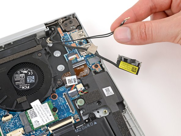
- Use your fingers to pull the display cable and two coaxial cables out from their clips on the right side of the fan.
- During reassembly, use this photo as a reference to properly route the cables into their clips.
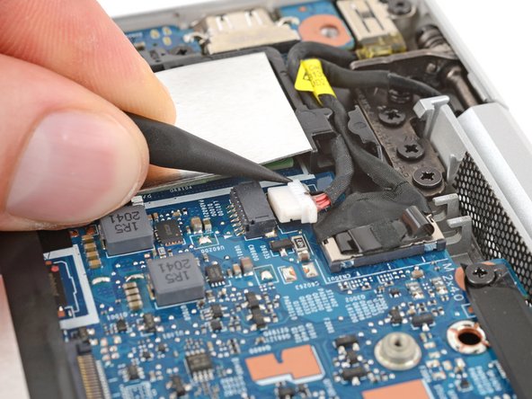
- Use the point of a spudger or your fingernail to push on alternating sides of the power connector's sliding connector to walk it completely out of its socket near the left hinge.
- During reassembly, make sure the side of the connector marked with a black dot is facing up before reconnecting the cable.
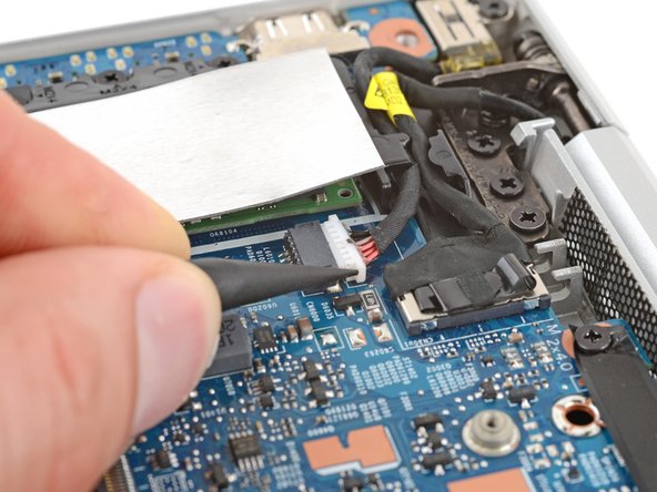
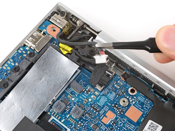
- Use tweezers or your fingers to pull the power connector cable out of its clip.
- During reassembly, use this photo as a reference to properly route the cable into its clips.
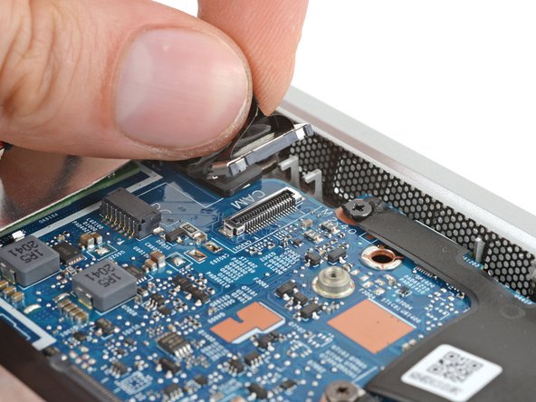
- Use your fingers to grip the plastic pull tab on the left display cable press connector, near the left hinge.
- Pull straight up to disconnect the connector.
- During reassembly, align the connector carefully over its socket and press down with your fingertip—first on one side, then the other—until it clicks into place. Don't try to force the connector into place. If you're having trouble, reposition it and try again. Don't use excessive force.
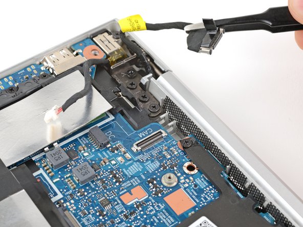
- Use tweezers or your fingers to pull the display cable out of its clip.
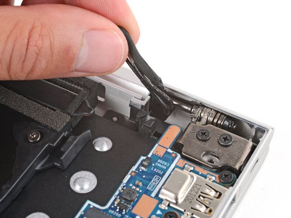
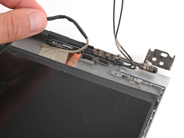
- Use your fingers or tweezers to lift the display and antenna cables out of their clip near the right hinge.
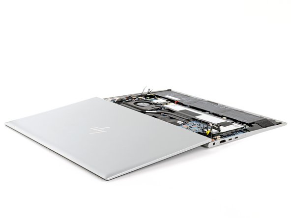
- Fully open your laptop and set it keyboard-side down on a flat, clean work surface, with the display closest you.
- During reassembly, if your screen clicks or snaps when it's opened or closed, loosen the screws and realign the screen.
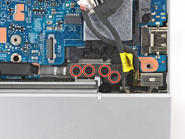
- Use a Phillips screwdriver to remove the six 4.6 mm‑long hinge screws—four in one hinge and two in the other.
- During reassembly:
- Before installing any hinge screws, make sure the display is properly aligned.
- Tighten the hinge screws in ascending order based on the number stamped next to each screw hole.
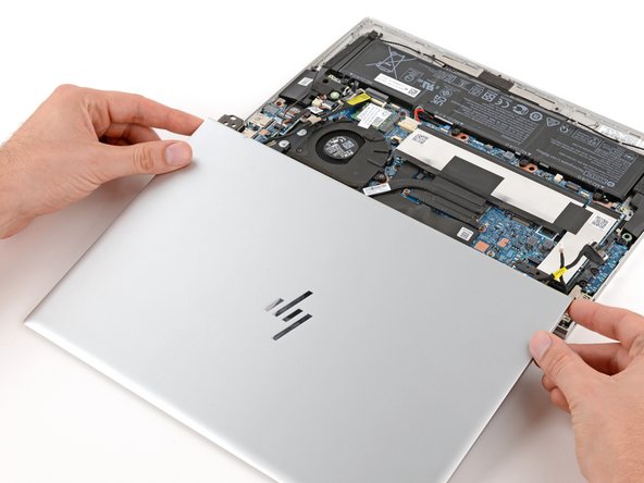
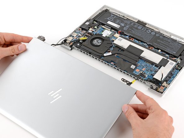
- Grip the display assembly near the hinges and lift straight up to remove it.
- You may need to hold down the main body while guiding the hinges out of their recesses.
- During reassembly, make sure both hinges on your replacement display assembly are fully open before lowering them into their recesses.
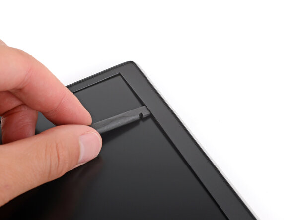
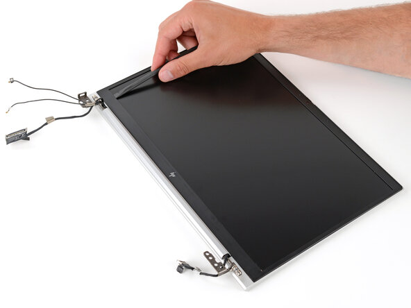
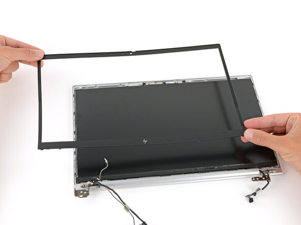
- Push the flat end of a spudger underneath the top edge of the display's plastic bezel, near the top left corner.
- The plastic bezel is bendable and secures to the display with light adhesive.
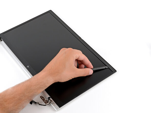
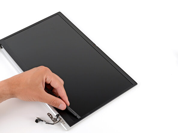
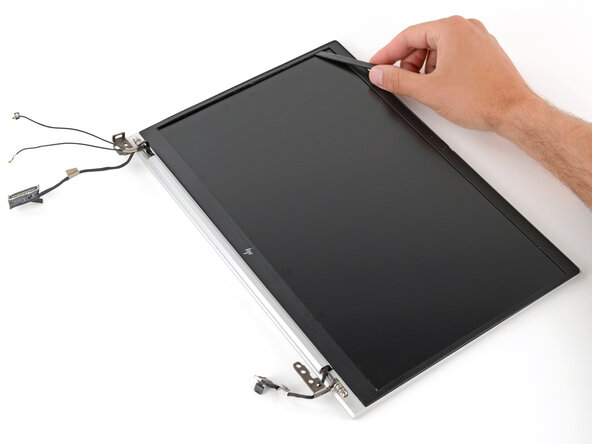
- Slide the spudger across the top edge, around the top right corner, and down the right edge to separate the adhesive securing the bezel.
- Slide the spudger across the bottom edge, around the bottom left corner, and up the left edge to separate the adhesive securing the bezel.
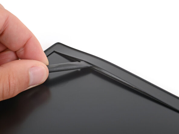
- Re-insert the flat end of the spudger underneath the top edge of the display's plastic bezel, near the top left corner.
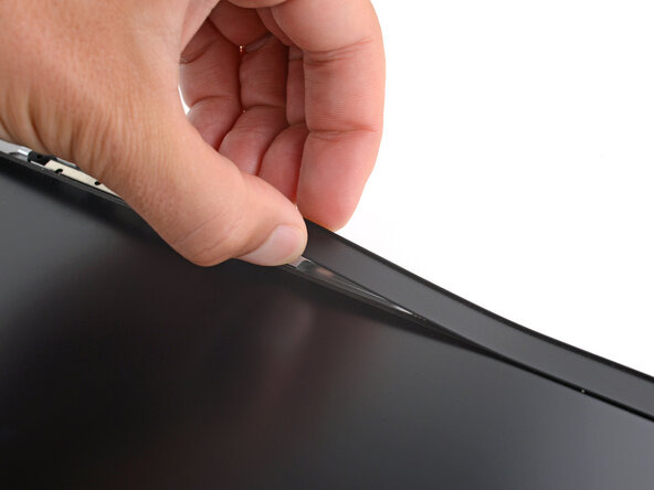
- Lift up to peel the bezel away from the display, until you can grip it with your fingers.
- Once a portion of the bezel lifts to where you can grip it with your fingers, peel the bezel up around the entire perimeter, using the spudger to separate any sections still adhered.
- Remove the plastic bezel.
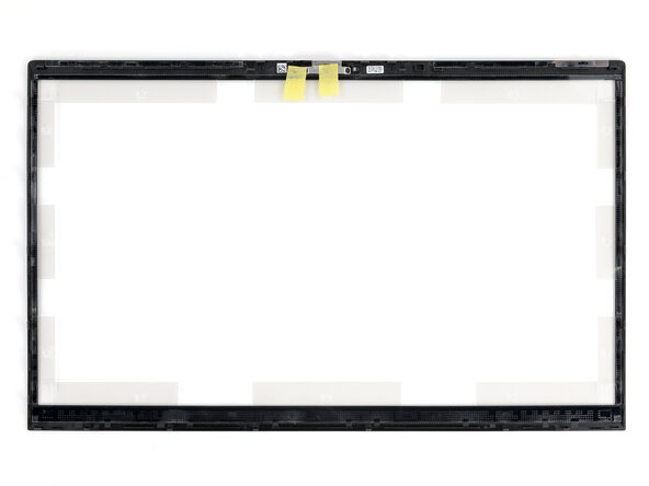
- During reassembly, make sure to remove all the plastic liners and pieces of tape from your replacement bezel. Check thoroughly around the entire perimeter.
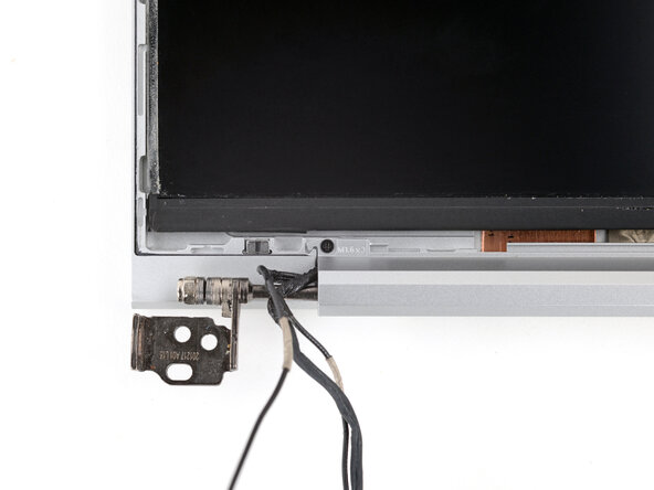
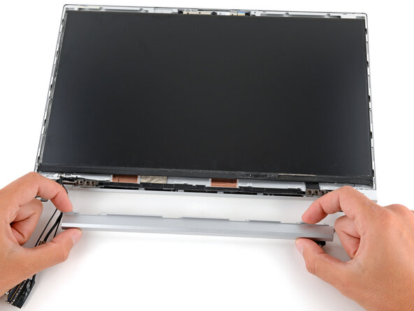
- Use a Phillips screwdriver to remove the 2.0 mm-long screw securing the chin cover.
- Slide the entire chin cover to the right to unlock it.
- Rotate the chin cover down and away from the display.
- Remove the chin cover.
- During reassembly:
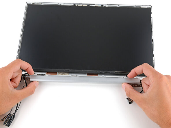
- Before reinstalling the chin cover, make sure all of the cables along the bottom of the screen are tucked into their recess and over the screen hinges. Use this photo as a reference.
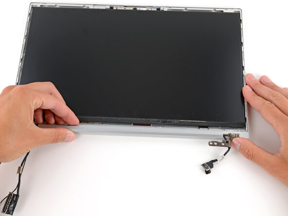
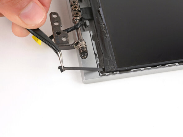
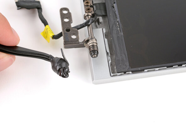
- The display panel attaches to the shell with two stretch-release adhesive strips.
- Near the bottom right side of the screen, use a pair of tweezers to peel back the black pull tab on the stretch-release adhesive strip until you can grip it with your fingers.
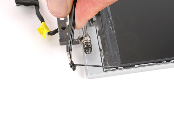
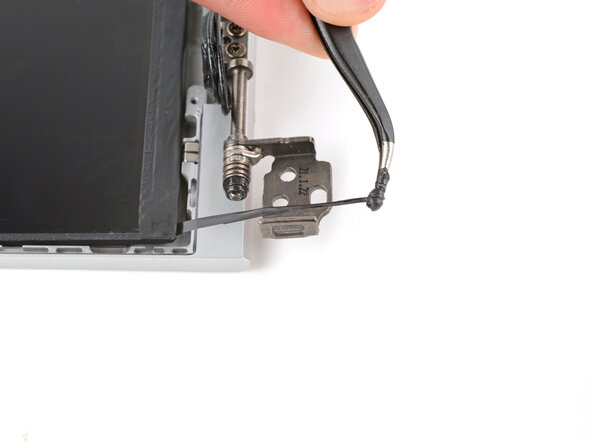
- Grab an adhesive strip's pull tab and slowly pull it out from underneath the screen.
- If using a pair of tweezers, spin the tweezers to wrap the strip up as it releases, pulling as you go.
- Keep the angle of the adhesive strip as parallel to the display as you can.
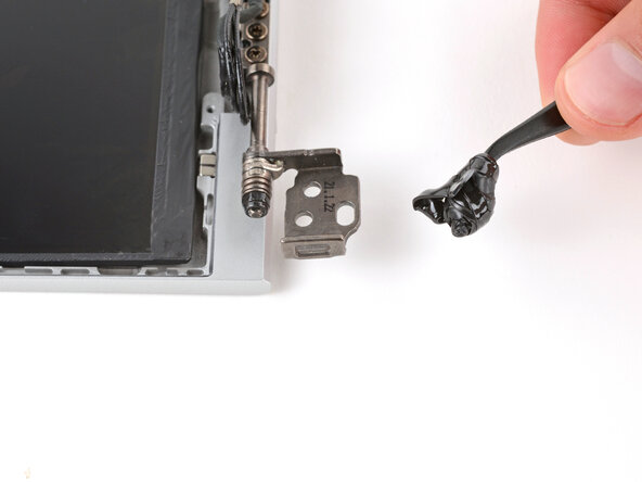
- Pull the adhesive strip until it's freed from under the screen.
- Repeat and remove the adhesive strip from the left side of the screen.
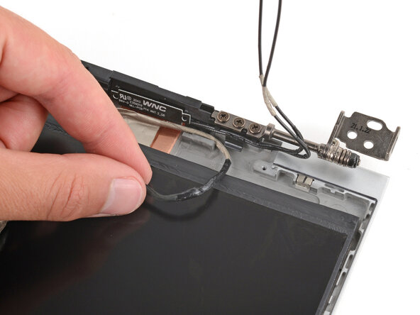
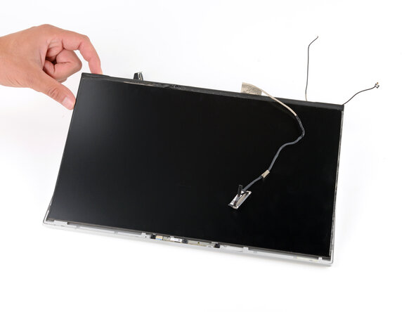
- Pull the display cable out from underneath its routing tab on the shell.
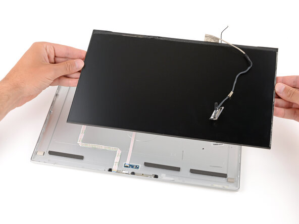
- Lift and remove the display panel from the shell.
- Replacement display panels may or may not come with an included display cable. If it's missing on the replacement, you'll need to transfer the old one over from your original panel.
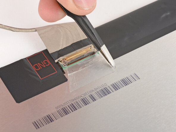
- A thin layer of tape covers and protects the display cable connector.
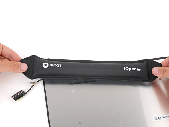
- Prepare an iOpener and apply it to the screen-side display connector tape for one minute to soften the adhesive.
- A hair dryer may also be used, but be careful not to overheat the components—keep the hair dryer well above the connector and moving at all times.
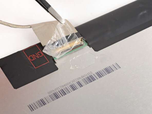
- Use the flat end of a spudger to push up a corner of the tape until you can grip it with a pair of tweezers.
- Use a pair of tweezers to peel the tape back, over the connector.
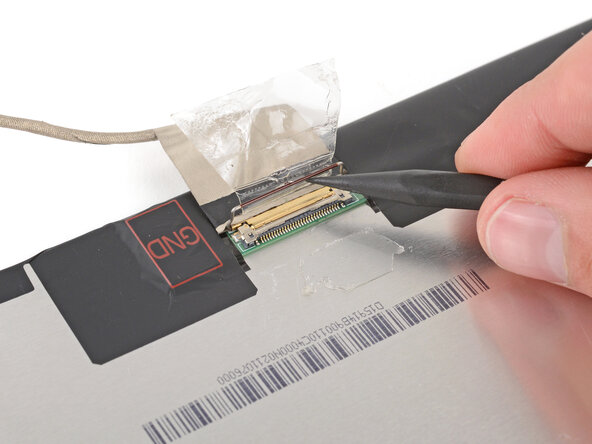
- Use the point of a spudger to lift up the thin metal locking bar on the display connector.
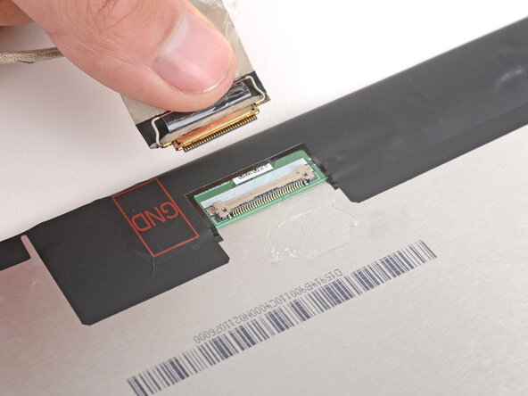
- Use your fingers to slide the display cable out of its connector.