why! V540TU Power Board Replacement
ID: 186272
Description: This guide shows you how to replace the power...
Steps:
- Unscrew the screws circled in red.
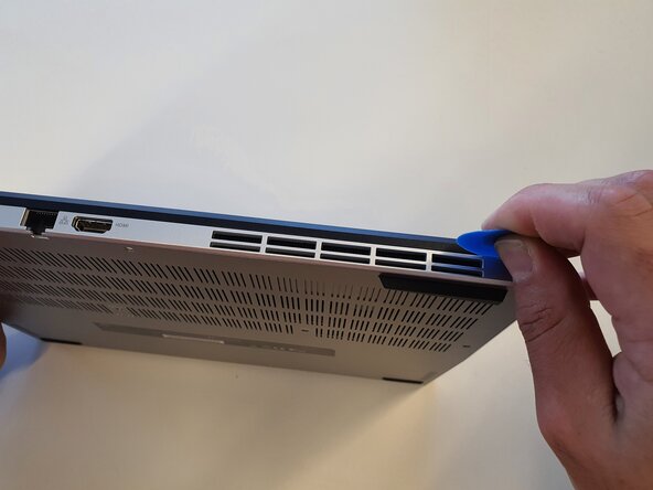
- Insert the opening pick into the gap and slide it all the way around.
- Unclip the housing at the corners.
- Lift the cover.
- Unplug the cable.
- Unscrew the screws circled in red and remove the battery.
- Insert the opening pick as shown and unclip the keyboard by sliding it along the entire length.
- Do the same for both sides.
- Gently lift the keyboard.
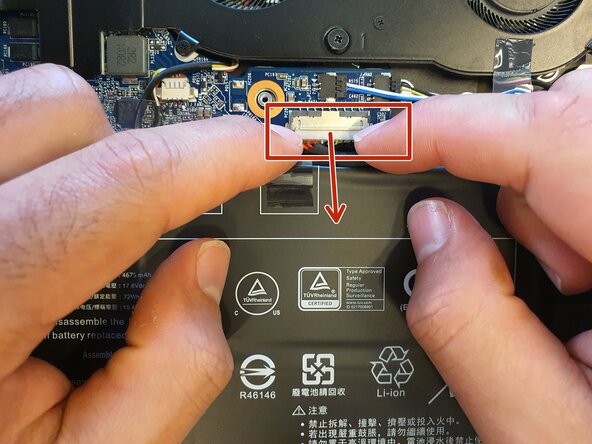
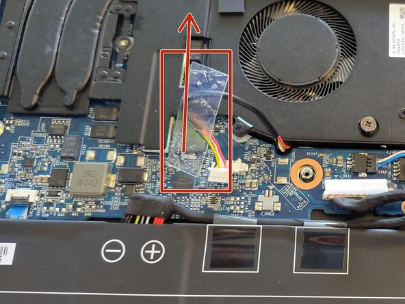
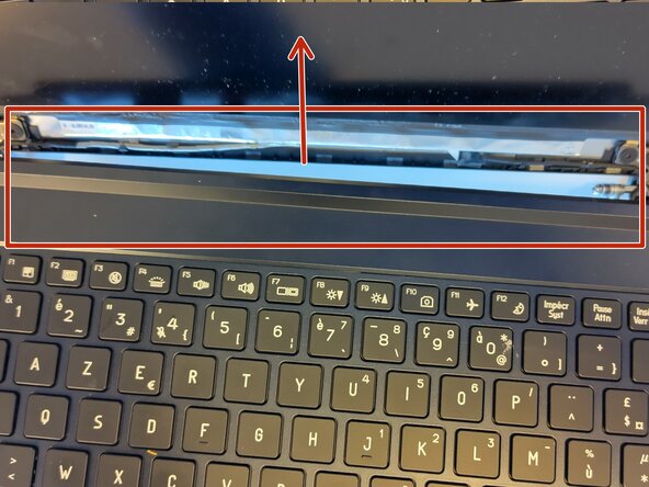
- Unclip and remove the connectors circled in red in the direction of the arrow.
- Remove the keyboard.
- Unscrew the screw.
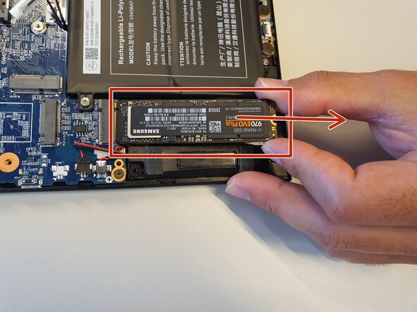
- Lift the SSD and remove it.
- Disconnect the cable.
- Remove the adhesive.
- Remove the speaker.
- Unplug the cable.
- Take out the speaker.
- Unplug the cable.
- Peel off the battery.
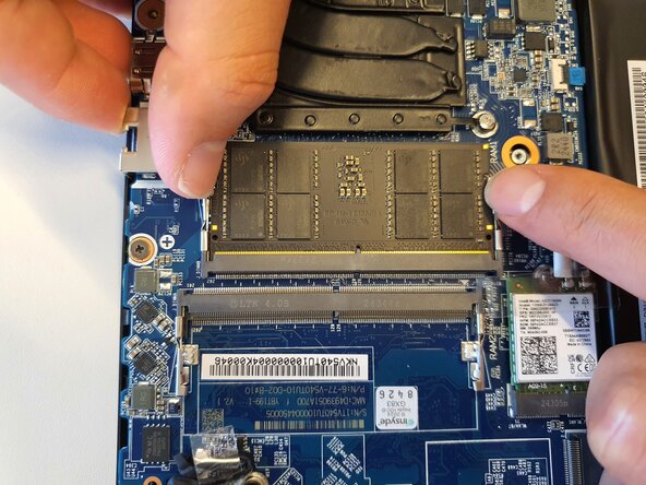
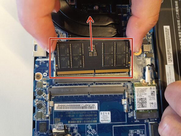
- Spread the two metal arms apart.
- Remove the RAM.
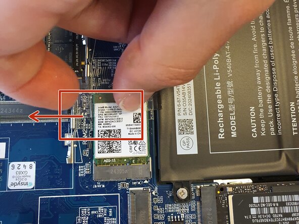
- Remove the adhesive.
- Unscrew the screw circled in red.
- Remove the Wi-Fi card.
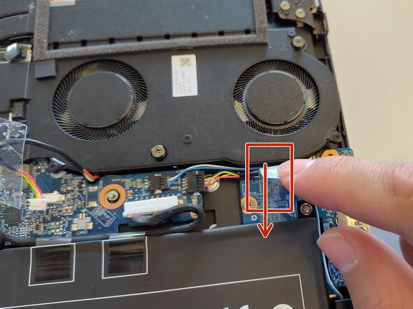
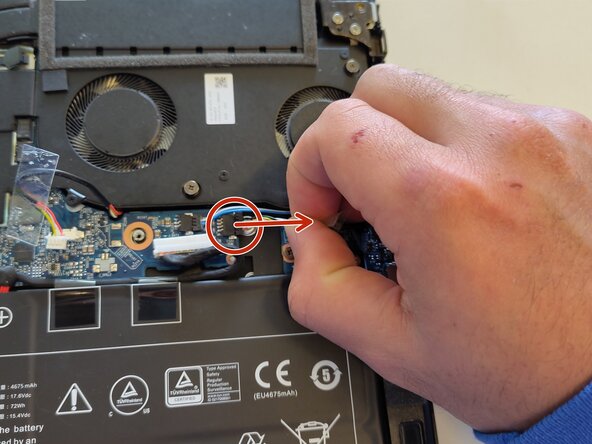
- Unclip the cables.
- Unscrew the screws circled in red.
- Remove the adhesive from the first cable.
- Remove the cable.
- Remove the second adhesive.
- Remove the second cable.
- Lift the heat sink.
- Unplug the cable connected to the motherboard.
- Remove the adhesives.
- Unscrew the screws circled in green.
- Lift the clutch hinge.
- Remove the cable.
- Remove the adhesive.
- Unscrew the screws circled in green.
- Reinstall the clutch hinge.
- Unplug the cable.
- Release the screen from the lower assembly.
- Unclip and remove the connectors circled in red.
- Rotate the device and place it in the position shown in the image.
- Unclip the two connectors circled in red.
- Flip the device over and unscrew the screws circled in red.
- Remove the motherboard.
- Unscrew the screws circled in red.
- Lift the board and carefully turn it over.
- Unclip the connector, pull it out, and remove the board.