2 - Microwave Oven - How It Works?
ID: 186288
Description: The purpose here is to see the different...
Steps:
- What is the cooking of a food? It is its chemical transformation through heat.
- Cooking allows for modifying the taste, flavor, appearance, color, texture, volume, weight, or nutritional qualities of food. It modifies its chemical and physical structure and can thus make it digestible, nourishing, or tastier, and sometimes eliminates toxicity.
- Exposing food to a heat source (fire, heat from an electric resistance…) will trigger reactions between its components. For instance, the Maillard reaction consists of an interaction between sugars and proteins, which gives your roast its taste!
- But what is heat, from a physics point of view? It is the level of agitation of molecules or atoms… A completely immobile molecule has a temperature equivalent to absolute zero, that is to say minus 273°C! Whereas the dioxygen molecules that float in a house wiggle at about 500 meters per second.
- A microwave oven, or more simply a microwave, is a household appliance used mainly for heating and quick cooking of food, by the agitation of the water molecules they contain, under the effect of microwave radiation.
- Microwaves are a type of wave located between radio waves and infrared radiation on the electromagnetic spectrum. In the case of microwave ovens, the wave frequency commonly used is approximately 2,450 megahertz (2.45 gigahertz).
- The electromagnetic field (2450 MHz) creates intense agitation of water molecules, which oscillate as microwaves pass through. Heat is generated by the friction of water molecules against one another. This thermal effect is therefore the result of the interaction between microwaves and water molecules.
- The penetration of microwaves into food items is linked to the power of the emitter. The direct thermal action is very intense at the surface and in the first few layers. Penetration gradually decreases with thickness.
- These waves also possess another interesting property: they are not absorbed by most plastics, glass, or ceramics. Metal reflects microwaves, which explains why metal pans do not work well in a microwave oven.
- This is also the reason why these appliances have metal walls, for reflection.
- Fig 1 The diagram helps to understand how the electromechanical ovens used by most manufacturers work, with the exception of a few options such as combination ovens or grill functions, which include additional heating elements.
- The electrical circuit consists of 3 parts: the power supply board Fig 2 connected to the socket. It is a small input electronic board equipped with a fuse and a few filtering components; this is the oven's main power supply.
- The power supply then passes through a series of safety systems: device overheating and door. The circuit also powers a lamp that illuminates the cavity, the motor that drives the turntable, the cooling fan motor for the magnetron, and the control board used to operate the device. Fig 3
- Once filtered and secured, the power supply is connected to the high voltage. This is the third part, composed of a transformer, a capacitor, and a diode, which are connected to the magnetron, the central component of the device.
- The electromechanical timer allows you to select the duration and cooking modes. It consists of a micro motor and 2 mechanical systems. A cam system manages the power regulator contact. A gear system manages the cooking duration contact.
- The micro motor is a synchronous motor powered by 230V. The winding resistance is on the order of several kΩ.
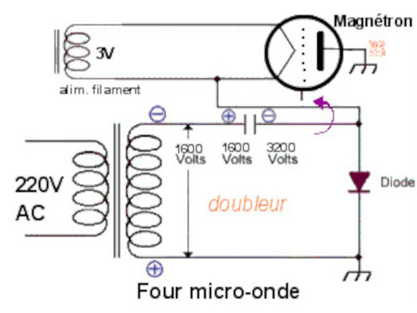
- The power circuit consists of a three-winding transformer (230V / HV – LV). The secondary of the transformer delivers 1600 Volts, which is necessary for creating the electric field. It consists of a very high number of turns. A voltage multiplier transforms this voltage into a 3200V voltage.
- The magnetron is the microwave generator. To function, it requires a current of 700 milliamperes at -3200V relative to ground. Our transformer produces 1600V; it is sufficient to double the voltage using a classic electronic circuit: a Latour doubler, also known as a Schenkel doubler.
- To double the voltage, the high voltage from the transformer is sent into a capacitor. At the output of the capacitor, there is a diode. There is also, and now almost systematically, a fuse on the high voltage circuit.
- A second winding powers the magnetron filament at a very low voltage of 3.2 V, but with a current of around 10 amperes.
- This consists of a cylindrical anode, or anode block. Electrons move from the cathode toward this anode, but due to the presence of magnets, a cloud of rotating electrons is formed.
- The charges then interact with the resonant cavities, oscillations that reverberate on adjacent vanes, creating a very high-frequency magnetic field (2,450 MHz, or 2.45 billion oscillations per second). An antenna is placed at the top, which collects the magnetic field and sends it toward the waveguide.
- The waves are brought to a stirrer, a wave fan, which projects them inside the oven. That is when they penetrate the food, or bounce off the walls and are reflected back toward the food.
- Cooking power regulation: It is not possible to modulate the emission power of the magnetron. To vary the cooking power, the magnetron's operating time is adjusted.
- Example: Minimum power (defrosting) ⇒ 10 seconds (every 30 seconds) Medium power (gentle cooking) ⇒ 20 seconds (every 30 seconds) Maximum power (high cooking) ⇒ 30 seconds (every 30 seconds)
- An electrical transformer is a converter that allows you to change the voltage and current intensity values delivered by an alternating electrical power source into a system of voltage and current with different values but the same frequency and form. It performs this transformation with excellent efficiency.
- In a static transformer, energy is transferred from the primary to the secondary via the magnetic circuit formed by the transformer's core.
- In the event that all losses and flux leakages are neglected, the ratio of the number of turns in the primary and secondary completely determines the transformation ratio of the transformer: U2/U1=N2/N1 U1=primary voltage U2=secondary voltage N1= number of primary turns N2= number of secondary turns
- The microwave transformer is a high-voltage transformer. It is used as a step-up transformer. It serves to provide high voltage to the magnetron. It consists of 3 windings: the primary winding powered at 230V, and two secondary windings providing 3.2V and 2100V.
- 3.2 volts are necessary for powering the cathode. The winding is of large diameter because the intensity exceeds 10A.
- 2100 volts are necessary to create the pulsed voltage between the anode and the cathode of the magnetron. The HV winding is of very small diameter because it only generates a weak current. One end of this winding is connected directly to the device's ground.
- The capacitor acts as a voltage doubler. It doubles the 1600V voltage from the secondary of the transformer to approximately 3200V.
- This non-polarized capacitor is built around a capacitance between 0.95 and 1.15 microfarads that stores electrical energy during a half-cycle, and a 10MΩ internal resistance that ensures its discharge.
- When the device is powered off, it is possible to have a voltage close to 4000 volts at its terminals. Even if it includes a discharge resistor and despite working with the power disconnected, it is ABSOLUTELY NECESSARY to discharge the capacitor before working on the other components of the oven.
- To do this, you can use a 1MΩ resistor to short-circuit the terminals of the capacitor. You can also use needle-nose pliers after waiting about ten minutes after having unplugged it from the mains socket.
- The function of a diode is to rectify alternating current into direct current.
- A diode allows current to pass in only one direction. There are several possible solutions for rectifying current. The one chosen to power the magnetron is a circuit with a single diode that powers the magnetron every other half-cycle (the positive half-cycle is conductive, the other half-cycle is blocked).
- Fig 1 During the half-cycle where the diode is non-conductive, a high-voltage capacitor is charged, which will then discharge during the half-cycle where the diode is conductive. The capacitor's voltage will add to that of the transformer to obtain the 4000 V voltage required to power the magnetron.
- The capacitor & diode assembly is called a voltage doubler because it allows the 2700 V alternating voltage from the transformer to be brought up to a 4000 V direct voltage.
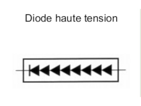
- The high-voltage diode is designed for a peak reverse voltage (Vr) on the order of 6000 volts. To withstand such a voltage, a simple PN junction is not enough. Several junctions must be stacked in series. The power diode is therefore a stack of eight diodes Fig 2.
- Due to this stacking, the HV diode cannot be checked using an ohmmeter.
- This is an optional component. It is mounted in parallel with the capacitor Fig 1. It consists of two back-to-back diodes with reverse breakdown voltages VD1 = 6000 Volts, VD2 = 1200 Volts Fig 2. It serves to protect the transformer in the event of a power diode short circuit.
- The goal is to create a clean short circuit that will blow the primary fuse. If the HV diode shorts, the capacitor finds itself in parallel with the HV secondary winding. This results in the equivalent schematics Fig 3.
- The voltage delivered is an alternating periodic voltage with a value of 3000 Volts max. Diode D2 breaks down and shorts. The current in D1 is too high and D1 also shorts. The secondary winding is short-circuited. An overcurrent occurs at the secondary, then at the primary.
- This overcurrent is such that the primary fuse blows. The transformer is protected.
- Fig 1 "Klixon" thermal switches. These are installed on the magnetron and the oven cavity. When the temperature exceeds the standards, the switches cut the power supply, thus protecting against excessive overheating incidents.
- Fig 2 In most cases, the microwave fuse is equipped with a spring in its structure. The fuse is made of fusible wire designed to withstand slow melting at a few hundred milliamperes (between 500 and 700 mA).
- The operation must happen very quickly to prevent an electric arc from forming. The spring is under mechanical tension. It is stretched. When the fusible wire melts, it returns to its original position, quickly separating the entry and exit points of the electric arc, blowing out the arc, just like blowing out a candle!
- This fuse is placed in a colored plastic insulating casing, usually red.
- Fig 3 The microwave oven is equipped with a door safety assembly. These door contacts, known as micro-switches, are there to protect the user from potential burns or injuries that the microwave generator would cause if the door remained open.
- When nothing is pressing on it, it is at rest. A micro-switch has three terminals. One terminal is the common (terminal 1), where the current "arrives." Opposite it, a type of switch! One contact closed at rest (terminal 2) and another open at rest (terminal 4).
- When the switch is pressed, the states reverse: contact 2 opens and contact 4 closes.
- Fig 1 Turntable motor: it is used to rotate dishes to evenly distribute heat in the food being heated.
- On some oven models, the turntable drive motor is powered by the cooling fan motor with 30 volts AC! It is remarkable that on some cooling fan models, there are three connectors: a live wire, a neutral wire, and the third shows a voltage of about thirty volts when measured.
- This intermediate voltage is taken from the coil of the cooling fan motor. It therefore acts both as a cooling fan and as an autotransformer to power the turntable motor.
- Fig 2 Cooling fan: it allows for: - Cooling the magnetron and the transformer - Renewing the air in the cavity to prevent condensation - Driving the wave stirrer (stirrer) in some cases. The motor is of the asynchronous type. The resistance of the winding is on the order of a hundred Ω.