Samsung Galaxy Tab 10.1 Motherboard Replacement
ID: 18738
Description: In this guide, you will learn how to replace...
Steps:
- Place the bottom of the tablet towards you.
- Remove the 4.1mm screws near the charge port with a Tri-Wing screwdriver.
- If there are plastic tabs covering these screws, use pointed tweezers to pry the tabs out.
- On model GT-P7500, this step is omitted, as that model doesn't have these 2 screws.
- Start in the middle of the left side and insert a plastic opening tool between the rear panel and the front panel assembly.
- Carefully run the plastic opening tool along the left and top edge to pry the rear panel away from the rest of the device.
- Place opening picks along the side you have already pried open to keep the back panel detached from the rest of the device.
- Be sure to work carefully, as prying too firmly can crack the screen.
- Using the plastic opening tools, continue to carefully run along the right and bottom edge, and then lift the screen from the back panel.
- Flip up the retaining flaps on the ZIF connectors that secure the three large ribbon cables.
- Carefully pull the three ribbon cables from their sockets on the motherboard.
- Remove the ten 3 mm Phillips #00 screws surrounding the battery.
- Lift the edge of the battery up with your finger or a spudger.
- Detach the battery by holding the motherboard down while gently lifting the battery up.
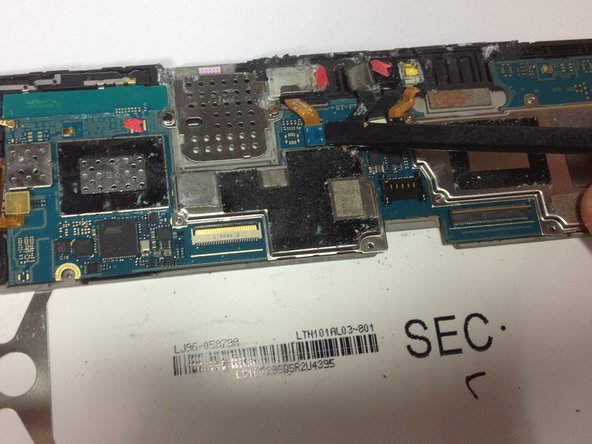
- Hold down the motherboard with your finger and use a spudger to gently pry up the connection for the volume keys and power key.
- Using the flat end of a spudger, disconnect the black flash cable connector from the motherboard.
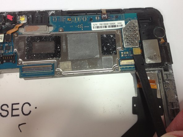
- Disconnect the white rear-facing camera connector.
- Use the flat end of a spudger to disconnect the orange front-facing camera connector.
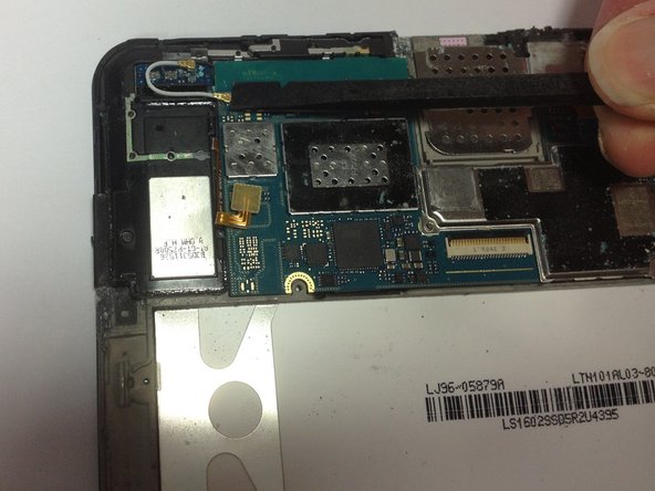
- Disconnect the blue Micro SD card/headphone jack connector from its socket on the motherboard.
- Using the flat end of a spudger, disconnect the orange speaker connectors for the left and right speakers.
- Disconnect the gold antenna cable connector from its socket on the motherboard.
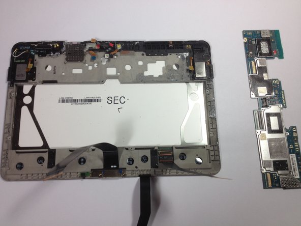
- Lifting from the bottom edge, gently remove the motherboard.