Philips 22PFL3504D Power Transformer Replacement
ID: 18982
Description: The most common issue with humming, and...
Steps:
- Here is the Philips 22PFL3504D. Fingerprints are definitely visible on the glossy front bezel and the LCD. those are really just smudges.
- Turn the TV over and lay it down,
- this will show the four Philips head screws that hold the base on to the TV
- With the four M3X15 mm screws removed, the base can be taken off.
- Remove the three Philips head screws on the right side
- Remove the three Philips head screws on the left side.
- Remove the two Philips head screws on the bottom
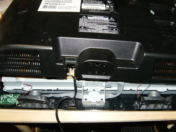
- The back cover can now be removed by simply lifting it up.
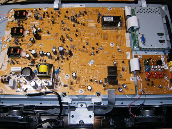
- Here is a view of the layout of this TV. Clean and tidy with only a few ribbon cables.
- Remove the three CCFL connectors
- Remove the top flat ribbon cable. it is a simple press fit and just needs to be pulled out.
- remove the two and flat ribbon cables from the video board,
- as well as the ribbon cable from the interface board.
- Remove the power button cable. It is a eight pin connetor and needs to be pulled up
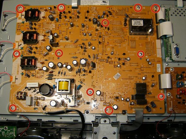
- Remove the twelve M3x6mm Philips head screws
- Remove the board from the TV
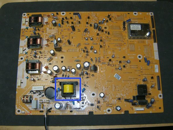
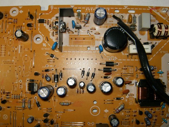
- this is the transformer that needs to be replaced.
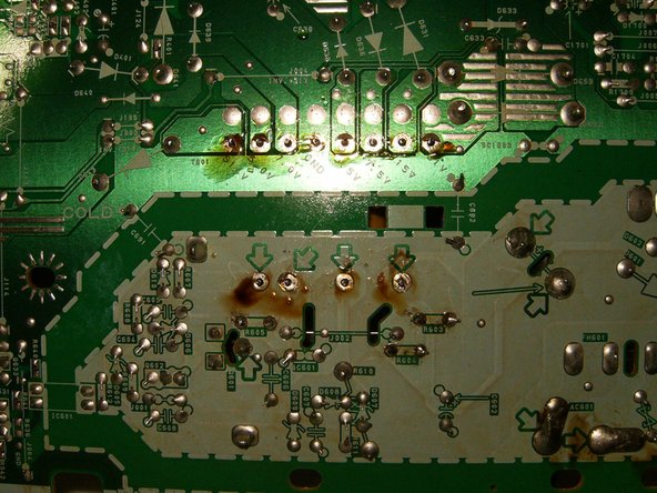
- Turn the board over so that the solder points are up. Identify the connections for the transformer
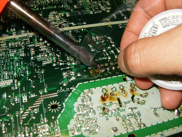
- Use some flux on the desolder wick and desolder the contacts.
- The wick leaves the contacts without any solder, which will help to easily remove the transformer.
- Turn the board component side up and remove the transformer
- Here is the board with the transformer removed.
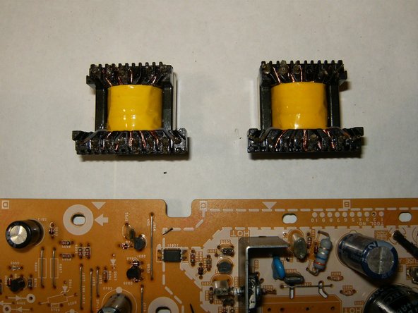
- Always make sure the the replacement parts are identical in size and contacts. I like to compare the old (right) to the new (left)
- Insert the new transformer gently through the holes on the board.
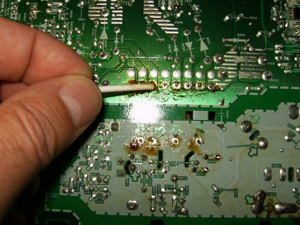
- Turn the logic board component side down, identify the transformer contacts. Apply some flux to the contacts.
- Solder the new transformer in place. The brownish residue is from the flux. The board can be cleaned with isopropyl alcohol after the solder repair.
- Ensure the all connections have been soldered and no accidental solder bridge was created. If it all looks satisfactory, reassemble the TV
- After the repair and reassembly. hopefully this is what you will see. A perfect picture and no disturbing humming