Canon EOS 6D Mark II DC/DC Power Board Replacement
ID: 190719
Description: This is my first guide on iFixit! Forgive the...
Steps:
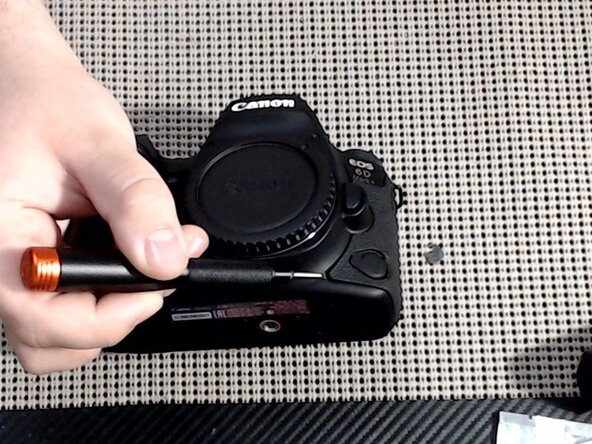
- Use a plastic pry tool (recommended), a small flathead screwdriver, or your fingernail, to pry up the rubber grips around the camera. There are 3 to remove.
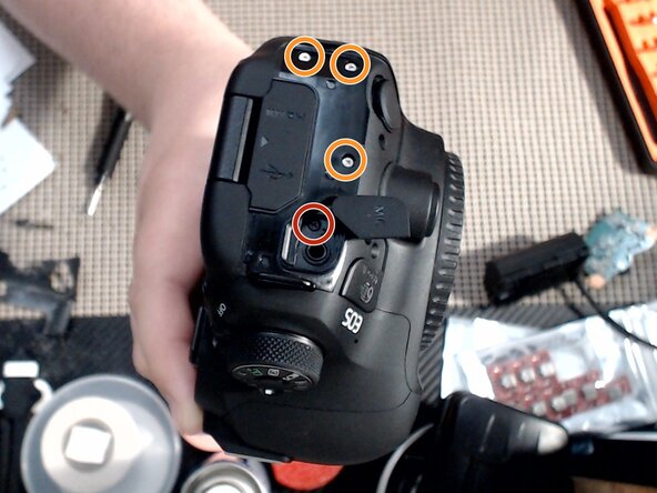
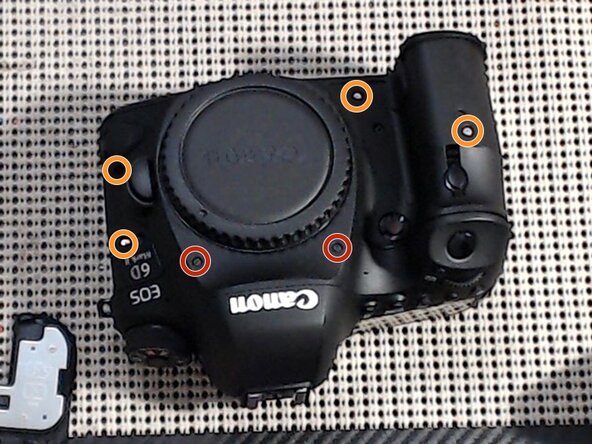
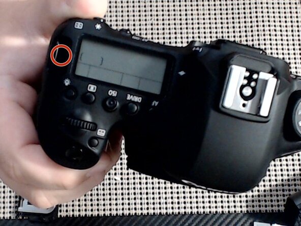
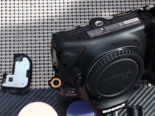
- Remove 1x Black Phillips 00 screw. (red marker)
- Remove 3x Silver Phillips 00 screw. (orange marker)
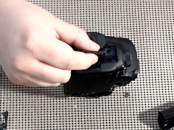
- Grip the HDMI/USB cover flap and gently pull away from the camera body. The bezel should come free from the camera.
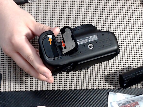
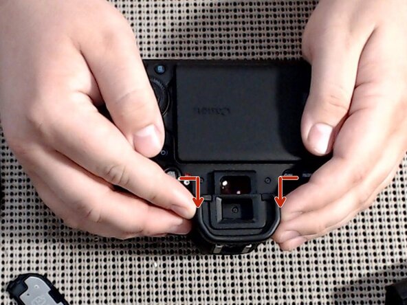
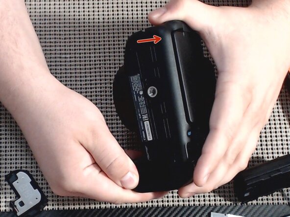
- Remove the battery. (orange arrow)
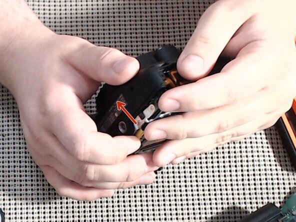
- Remove the battery cover by gently pressing the cover-removal tab towards the rear of the camera. (red arrow)
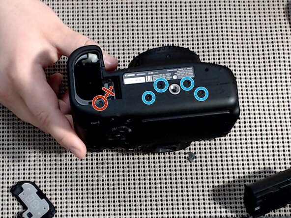
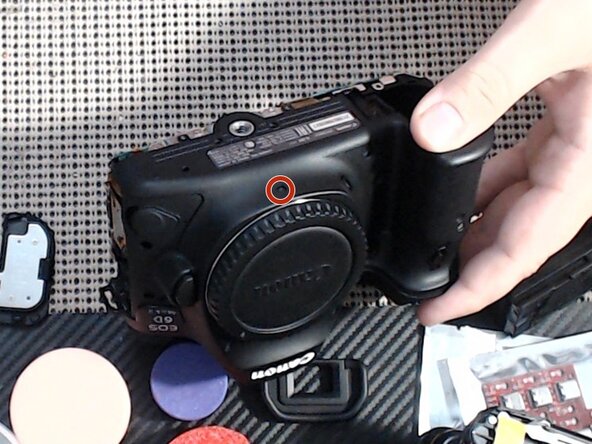
- Remove 1x Black Phillips 00 screw. (red marker)
- Remove 4x Short Black Phillips 00 screws. (blue markers)
- DO NOT remove screw for the battery cover bracket base! (red X) If this screw is removed, this part will fall free during disassembly, and putting it back in place can be a pain!
- Squeeze the eye relief at the sides and push towards the top of the camera to remove.
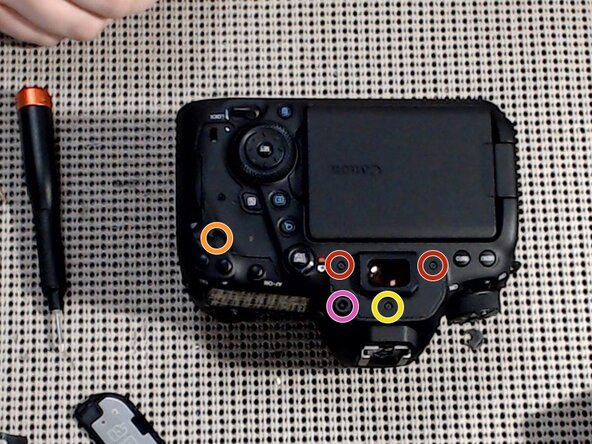
- Remove 1x Silver Phillips 00 screw. (orange marker)
- Remove 2x Black Phillips 00 screws. (red markers)
- Remove 1x Short Black Phillips 00 screw. (yellow marker)
- Remove the diopter adjustment by unscrewing its Phillips 00 screw. (pink marker)
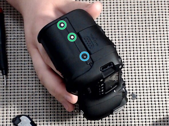
- Remove 2x Short Silver Phillips 00 screws. (green markers)
- Remove 1x Short Black Phillips 00 screws. (blue marker)
- Remove 2x Silver Phillips 00 screws. (orange marker)
- Gently pry the back cover away from the camera body. Ensure there is no SD card in the camera, or this step will be very difficult, or you may break the SD card or the camera main board!
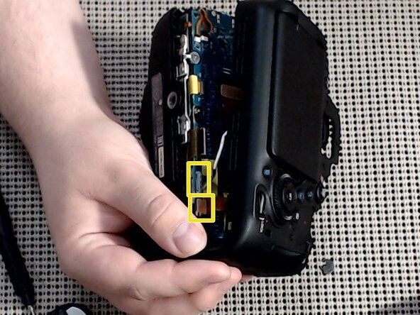
- Gently disconnect 2 cables (yellow marker) before setting the back cover aside.
- Remove 4x Silver Phillips 00 screws from around the grips. (orange markers)
- Remove 3x Black Phillips 00 screws from around the lens mount. (red markers)
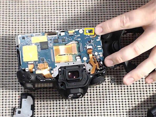
- Disconnect 1 tiny ribbon cable from the corner of the main board. It's the one closest to the corner, the smallest one.
- Gently pry the front cover away from the camera body. I find that if you start at the bottom around the tripod screw, this is easier.
- Gently disconnect 3 cables and 1 connector from the main board.
- Remove 1x Black Phillips 00 screw from above the right-hand strap loop. (red marker)
- Remove 1x Silver Phillips 00 screw from underneath the left-hand strap loop. (orange marker)
- Lift away the top cover from the camera body.
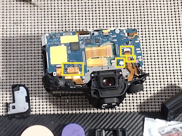
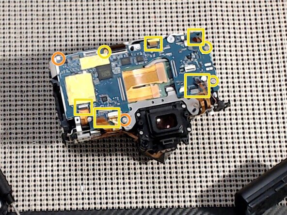
- Disconnect all cables except the large main one in the center. (yellow square markers)
- Remove 2x Silver Phillips 00 screws. (orange markers)
- Remove 3x Short Silver Phillips 00 screws. (yellow markers)
- Remove 2x Silver Phillips 00 screws. (orange markers)
- Remove 2x Short Silver Phillips 00 screws. (yellow markers)
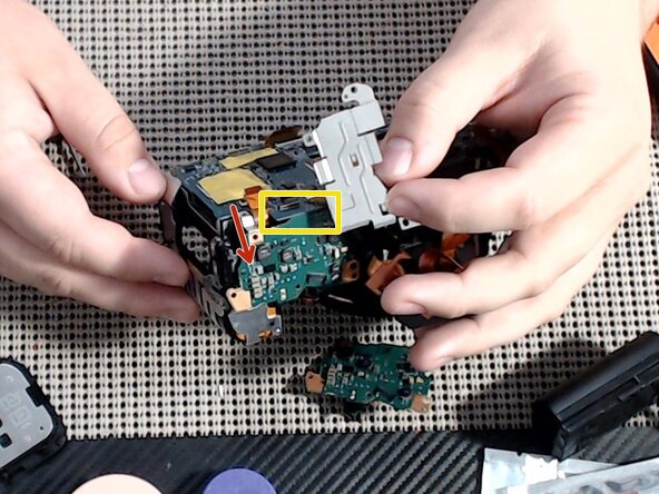
- Gently lift the power board away from the camera body, and separate the main board from it. They have a connector hidden underneath. (yellow marker)
- The power board should now be free to remove and service/replace.