Framework Desktop Mainboard Installation (Mainboard Replacement)
ID: 191550
Description:
Steps:
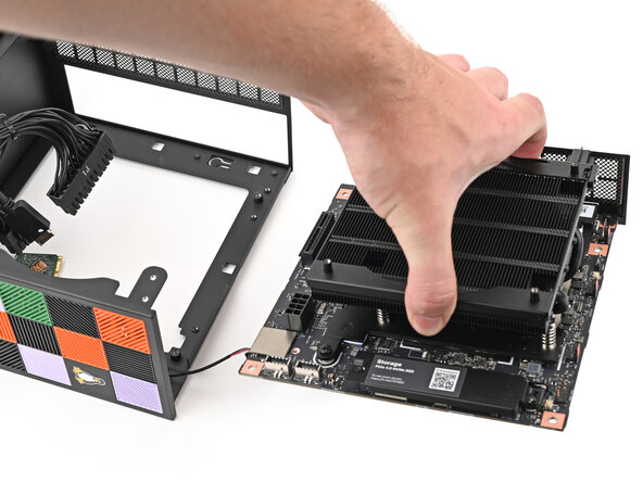
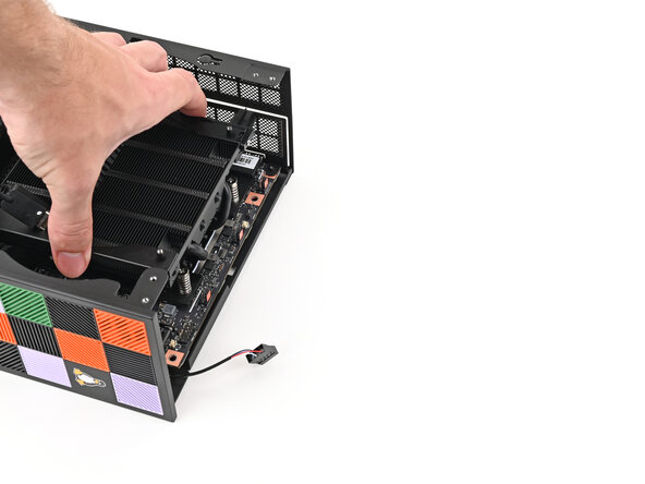
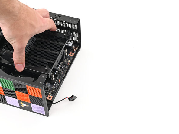
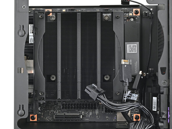
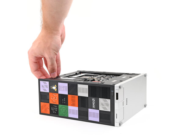
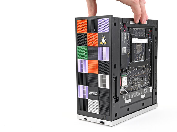
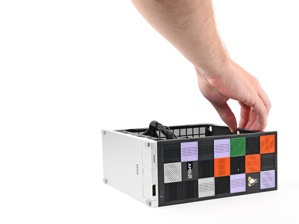
- Grab the Mainboard by its heatsink and slide it into the chassis.
- Align the rear ports with its cutout and the screw posts with the screw holes on the Mainboard.
- You'll feel the Mainboard rest onto the screw posts when it's aligned properly.
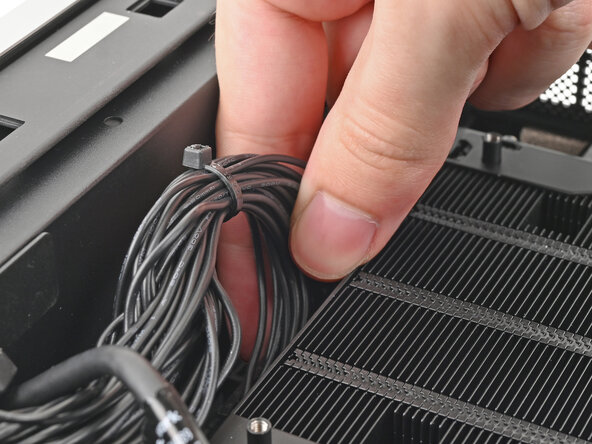
- Make sure no cables are trapped underneath the Mainboard before continuing.
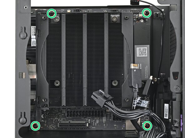
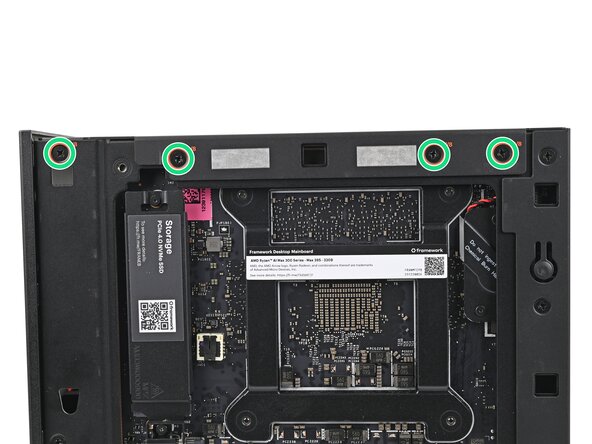
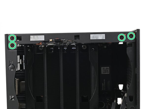
- Use your Framework Desktop Screwdriver to install the four 8.2 mm‑long Phillips screws securing the Mainboard.
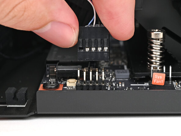
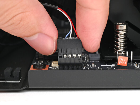
- Slide the power button cable over the nine-pronged connector on the Mainboard.
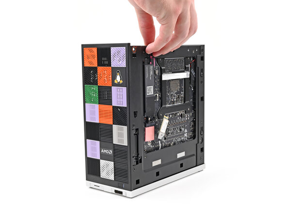
- Rotate the Desktop onto its left side so the underside of the Mainboard is facing upward.
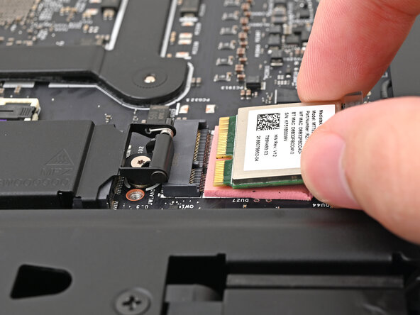
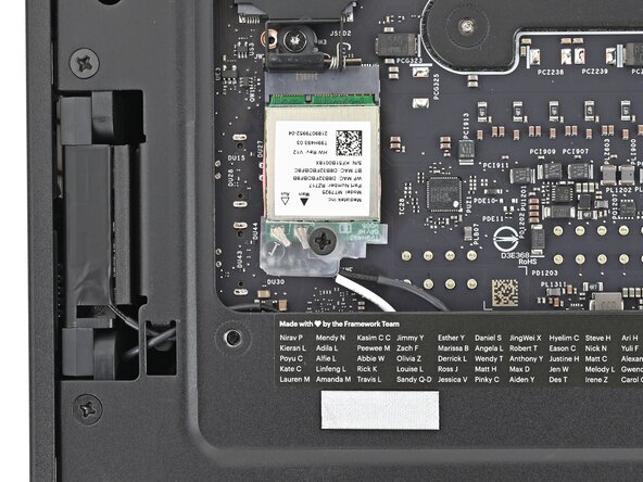
- Hold the Wi-Fi module by its edges. Don't touch the gold contacts with your fingers. If you do, wipe the contacts with a clean, lint-free cloth to remove any finger oils.
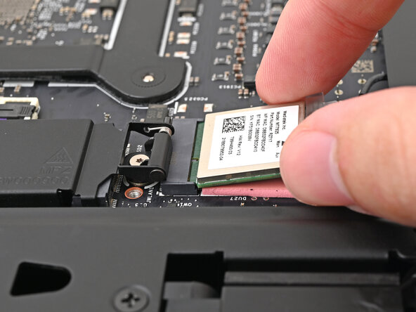
- Align the Wi-Fi module's gold contacts and notch with the socket on the Mainboard.
- Insert the Wi-Fi module into the socket at a shallow angle. The gold contacts should mostly be covered by the socket.
- The Wi-Fi module fits into the socket in one orientation. If it doesn't fit, try flipping the module.
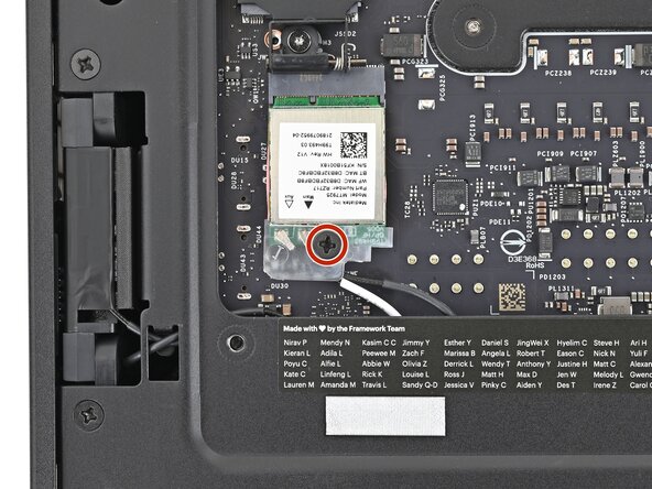
- Use your Framework Desktop Screwdriver to install the 7.0 mm‑long Phillips screw securing the Wi-Fi module.
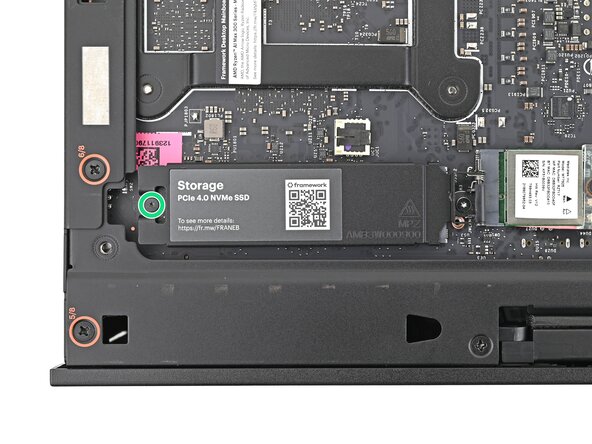
- Use your Framework Desktop Screwdriver to loosen the captive T5 Torx screw securing the heat spreader.
- If you want to install secondary storage, follow the next two steps. Otherwise, skip here.
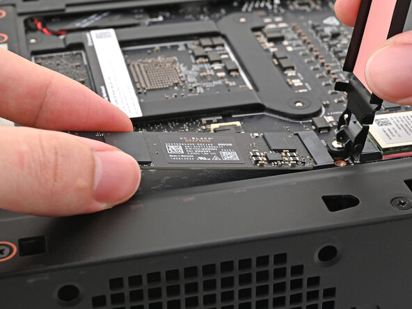
- Hold the SSD by its edges. Don't touch the gold contacts with your fingers. If you do, wipe the contacts with a clean, lint-free cloth to remove any finger oils.
- While holding the SSD heat spreader upright, align the SSD's gold contacts with its socket.
- Insert the SSD into the socket at a shallow angle. The gold contacts should mostly be covered by the socket.
- The SSD fits into the socket in one orientation. If it doesn't feel like it fits, try flipping the module.
- Lay the heat spreader back onto the SSD.
- Use your Framework Desktop Screwdriver to tighten the captive T5 Torx screw securing the SSD.
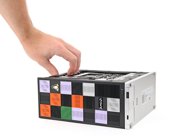
- Rotate the Desktop so it sits upright on your work surface.
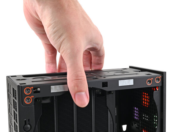
- Place the top plate on top of the Desktop, making sure it slots into the chassis so the orange circles are visible.
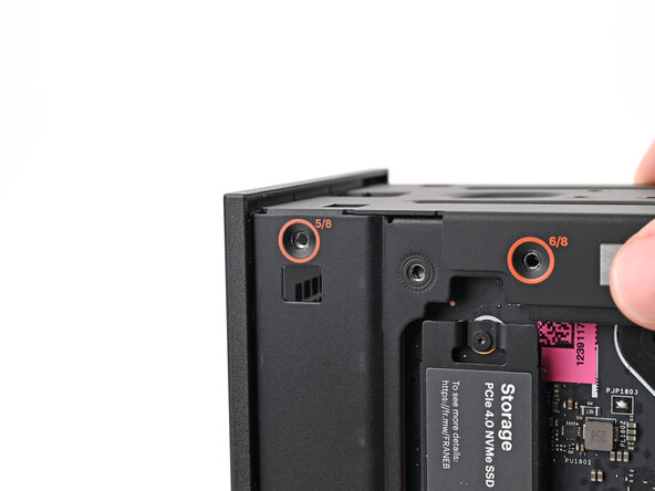
- Make sure the matching screw hole on the top plate labeled "5/8" is slotted on the inside of the Chassis so that the orange circle is visible.
- While holding the Desktop steady, use your Framework Desktop Screwdriver to install the eight 4.0 mm‑long Phillips screws securing the top plate.
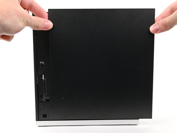
- Slide the Right Panel onto the right edge of the chassis, from top to bottom, and press it flat to ensure its clips are slotted into place.
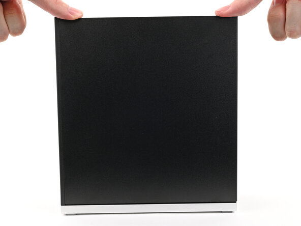
- There should be a small gap between the bottom of the Right Panel and the silver base.
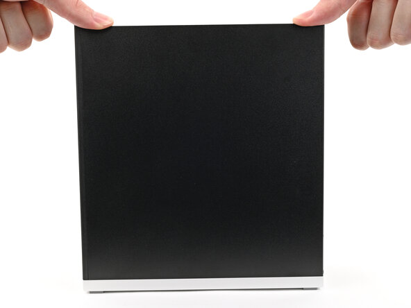
- Push the Right Panel towards the base of the computer to engage the clips.
- Lay the right side of the Desktop on your work surface so the Mainboard is facing upward.
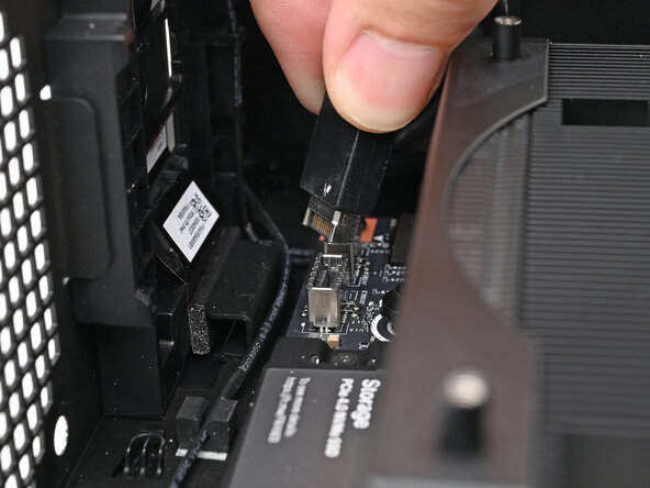
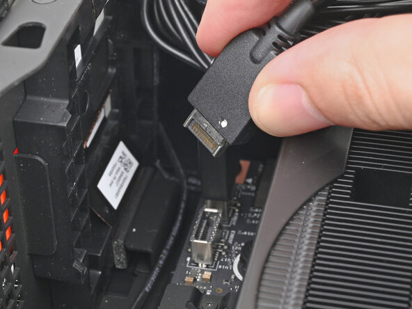
- Slide the bottom Expansion Card cable into its socket on the Mainboard.
- Orient the CPU power supply cable so its clip is facing the heatsink.
- Slide the cable into its socket on the Mainboard until you feel it click into place.
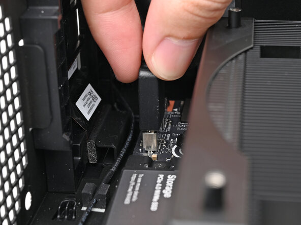
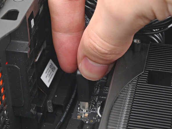
- Orient the main power supply cable so its clip is facing away from the heatsink.
- Slide the cable into its socket on the Mainboard until you feel it click into place.
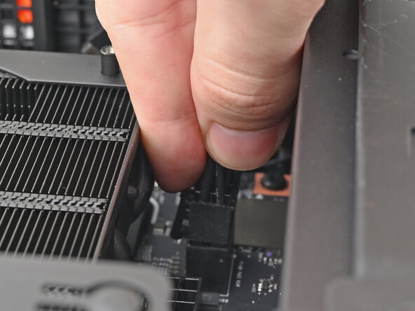
- Slide the top Expansion Card cable into its socket on the Mainboard.